This is the full developer documentation for BRM Lasers Support
# BRM Lasers support
### [Getting started](en/getting-started)
Here you will find everything you need to start working with the BRM Laser.
***
[Determining focal length](/en/getting-started/determining-focal-lengths)
[>](/en/getting-started/determining-focal-lengths)
[Different lenses](/en/getting-started/different-lenses)
[>](/en/getting-started/different-lenses)
[Focus distance (different lenses)](/en/getting-started/focus-distance-different-lenses)
[>](/en/getting-started/focus-distance-different-lenses)
[Lens assembly](/en/getting-started/lens-assembly)
[>](/en/getting-started/lens-assembly)
[Lens compatibility by machine model](/en/getting-started/lens-compatibility)
[>](/en/getting-started/lens-compatibility)
[Check all 6 articles](en/getting-started)
### [Maintenance](en/maintenance)
Find out how best to maintain your machine.
***
[Everything you need to know about the guides of the BRM Original](/en/maintenance/guidelines/guidelines-of-the-brm-original)
[>](/en/maintenance/guidelines/guidelines-of-the-brm-original)
[Cleaning mirrors](/en/maintenance/optical-path/cleaning-mirrors)
[>](/en/maintenance/optical-path/cleaning-mirrors)
[Cleaning the laser source](/en/maintenance/optical-path/cleaning-the-laser-source)
[>](/en/maintenance/optical-path/cleaning-the-laser-source)
[Lens cleaning](/en/maintenance/optical-path/lens-cleaning)
[>](/en/maintenance/optical-path/lens-cleaning)
[Mirror alignment](/en/maintenance/optical-path/mirror-alignment)
[>](/en/maintenance/optical-path/mirror-alignment)
[Check all 6 articles](en/maintenance)
### [Material & parameters](en/materials-and-parameters)
Check here to see if your material is suitable and for associated parameters.
***
[CerMark LMM-6000](/en/materials-and-parameters/lasersprays/cermark-lmm6000)
[>](/en/materials-and-parameters/lasersprays/cermark-lmm6000)
[CerMark LMC-6044P](/en/materials-and-parameters/lasersprays/cermark-lmm6044p)
[>](/en/materials-and-parameters/lasersprays/cermark-lmm6044p)
[CerMark Ultra](/en/materials-and-parameters/lasersprays/cermark-ultra)
[>](/en/materials-and-parameters/lasersprays/cermark-ultra)
[TherMark LMM-14](/en/materials-and-parameters/lasersprays/thermark-lmm14)
[>](/en/materials-and-parameters/lasersprays/thermark-lmm14)
[Why use a laserspray](/en/materials-and-parameters/lasersprays/why-use-a-laserspray)
[>](/en/materials-and-parameters/lasersprays/why-use-a-laserspray)
[Check all 9 articles](en/materials-and-parameters)
### [Downloads](en/downloads)
Download software and important documentation related to your laser machine and associated peripherals here.
***
[Datasheets for the filters of the BRM Extractor](/en/downloads/datasheets/extractor-filters)
[>](/en/downloads/datasheets/extractor-filters)
[Specifications of non-filtering extraction](/en/downloads/datasheets/fume-extractor-non-filtering)
[>](/en/downloads/datasheets/fume-extractor-non-filtering)
[Peripheral device manuals](/en/downloads/manuals/peripheral)
[>](/en/downloads/manuals/peripheral)
[CerMark MSDSs](/en/downloads/msds/cermark)
[>](/en/downloads/msds/cermark)
[Safety Datasheet ZincSelenide (ZnSe)](/en/downloads/msds/lenses)
[>](/en/downloads/msds/lenses)
[Check all 7 articles](en/downloads)
### [Peripherals](en/peripherals)
Find all information regarding the peripherals of your laser machine here.
***
[Compressor option](/en/peripherals/air-supply/compressor-option)
[>](/en/peripherals/air-supply/compressor-option)
[How does the air supply work on my Pro laser machine?](/en/peripherals/air-supply/how-does-the-air-supply-work-on-my-brm-pro)
[>](/en/peripherals/air-supply/how-does-the-air-supply-work-on-my-brm-pro)
[How does the standard air pump included with the BRM Budget work?](/en/peripherals/air-supply/how-does-the-supplied-air-pump-work-with-the-brm-budget)
[>](/en/peripherals/air-supply/how-does-the-supplied-air-pump-work-with-the-brm-budget)
[How does the standard air pump supplied with the BRM Original work?](/en/peripherals/air-supply/how-does-the-supplied-air-pump-work-with-the-brm-original)
[>](/en/peripherals/air-supply/how-does-the-supplied-air-pump-work-with-the-brm-original)
[How does the standard air pump included with the BRM Slim work?](/en/peripherals/air-supply/how-does-the-supplied-air-pump-work-with-the-brm-slim)
[>](/en/peripherals/air-supply/how-does-the-supplied-air-pump-work-with-the-brm-slim)
[Check all 11 articles](en/peripherals)
### [Software support](en/software-support)
Check here for information or if you have a question regarding laser software.
***
[How can I load the machine profile into LightBurn?](/en/software-support/lightburn/how-can-i-load-the-machine-profile-into-lightburn)
[>](/en/software-support/lightburn/how-can-i-load-the-machine-profile-into-lightburn)
[How do i create a BRM machine in LightBurn (2.0 and above)?](/en/software-support/lightburn/how-do-i-create-a-brm-machine-in-lightburn)
[>](/en/software-support/lightburn/how-do-i-create-a-brm-machine-in-lightburn)
[How do I create a machine profile in LightBurn (1.9 and earlier)?](/en/software-support/lightburn/how-do-i-create-a-machine-profile-in-lightburn)
[>](/en/software-support/lightburn/how-do-i-create-a-machine-profile-in-lightburn)
[How do I activate and deactivate my LightBurn license?](/en/software-support/lightburn/how-to-activate-and-deactivate-lightburn)
[>](/en/software-support/lightburn/how-to-activate-and-deactivate-lightburn)
[How to install LightBurn?](/en/software-support/lightburn/how-to-install-lightburn)
[>](/en/software-support/lightburn/how-to-install-lightburn)
[Check all 6 articles](en/software-support)
### [Problems & Solutions](en/problems-and-solutions)
Find the solution to your problem here.
***
[Adjust and replace belts of the X- and Y-axes of the BRM Original](/en/problems-and-solutions/co2-machines/brm-original-belts-of-the-x--and-y--axes-adjustment-and-replacement)
[>](/en/problems-and-solutions/co2-machines/brm-original-belts-of-the-x--and-y--axes-adjustment-and-replacement)
[Help, I have a double line in my cutting and engraving](/en/problems-and-solutions/co2-machines/help-there-is-a-double-line-in-my-cutting-and-engraving-work)
[>](/en/problems-and-solutions/co2-machines/help-there-is-a-double-line-in-my-cutting-and-engraving-work)
[Machine protected error on the BRM Slim](/en/problems-and-solutions/co2-machines/machine-protected-error-on-the-slim)
[>](/en/problems-and-solutions/co2-machines/machine-protected-error-on-the-slim)
[Potential error messages on the machine](/en/problems-and-solutions/co2-machines/potential-error-messages-on-the-machine)
[>](/en/problems-and-solutions/co2-machines/potential-error-messages-on-the-machine)
[Shapes do not connect](/en/problems-and-solutions/co2-machines/shapes-do-not-connect)
[>](/en/problems-and-solutions/co2-machines/shapes-do-not-connect)
[Check all 19 articles](en/problems-and-solutions)
### [Tips and Tricks](en/tips-and-tricks)
Here are tips to get more out of your laser machine.
***
[Focus height tools](/en/tips-and-tricks/focus-height-tool)
[>](/en/tips-and-tricks/focus-height-tool)
[Can the laser machine and water chiller withstand the cold?](/en/tips-and-tricks/machines/can-the-laser-machine-and-water-chiller-withstand-the-cold)
[>](/en/tips-and-tricks/machines/can-the-laser-machine-and-water-chiller-withstand-the-cold)
[How do I adjust the auto focus of my BRM Slim and Pro?](/en/tips-and-tricks/machines/how-do-i-adjust-the-autofocus-of-the-slim-and-pro)
[>](/en/tips-and-tricks/machines/how-do-i-adjust-the-autofocus-of-the-slim-and-pro)
[These things are important to know before moving your laser machine](/en/tips-and-tricks/machines/it-is-important-to-know-these-things-before-moving-your-laser-machine)
[>](/en/tips-and-tricks/machines/it-is-important-to-know-these-things-before-moving-your-laser-machine)
[What can you do about reflection on your material?](/en/tips-and-tricks/machines/what-can-you-do-about-reflection-on-the-underside-of-your-material)
[>](/en/tips-and-tricks/machines/what-can-you-do-about-reflection-on-the-underside-of-your-material)
[Check all 9 articles](en/tips-and-tricks)
# Downloads
### Datasheets
***
[Datasheets for the filters of the BRM ExtractorDatasheets for the filters of the BRM Extractor.](/en/downloads/datasheets/extractor-filters)
[>](/en/downloads/datasheets/extractor-filters)
[Specifications of non-filtering extractionSpecifications of non-filtering extraction](/en/downloads/datasheets/fume-extractor-non-filtering)
[>](/en/downloads/datasheets/fume-extractor-non-filtering)
### Manuals
***
[Peripheral device manualsManuals for peripheral devices](/en/downloads/manuals/peripheral)
[>](/en/downloads/manuals/peripheral)
### MSDS
***
[CerMark MSDSsMaterial safety data sheets for CerMark products](/en/downloads/msds/cermark)
[>](/en/downloads/msds/cermark)
[Safety Datasheet ZincSelenide (ZnSe)Safety Datasheet ZincSelenide (ZnSe)](/en/downloads/msds/lenses)
[>](/en/downloads/msds/lenses)
[Optical materialsThis lists all msds'es for the optical materials used](/en/downloads/msds/optical-materials)
[>](/en/downloads/msds/optical-materials)
### Software
***
[CAD/CAM laser softwareCADCAM laser software downloads for BRM lasers](/en/downloads/software/cad-cam-laser-software)
[>](/en/downloads/software/cad-cam-laser-software)
# Datasheets for the filters of the BRM Extractor
> Datasheets for the filters of the BRM Extractor.
## Pre filters
[Section titled “Pre filters”](#pre-filters)
| Naam | Voor extractor | Versie | Laatst geüpdatet | URL |
| -------- | ------------------------ | ------ | ---------------- | ------------------------------------------------------- |
| A1030153 | BRM Extractor S | 1 | 22-06-2018 | [Download](/assets/docs/DS/A1030153.pdf) |
| A1030156 | BRM Extractor M | 1 | 21-06-2018 | [Download](/assets/docs/DS/EFS00002%20-%20A1030156.pdf) |
| A1030222 | BRM Extractor L t/m XXXL | 1 | 01-08-2018 | [Download](/assets/docs/DS/EFS00036%20-%20A1030222.pdf) |
| A1030190 | BOFA AD Nano | 1 | 02-08-2018 | [Download](/assets/docs/DS/EFS00029-A1030190.pdf) |
## Combined filters
[Section titled “Combined filters”](#combined-filters)
| Naam | Voor extractor | Versie | Laatst geüpdatet | URL |
| -------- | ------------------------ | ------ | ---------------- | ------------------------------------------------------- |
| A1030154 | BRM Extractor S | 1 | 22-06-2018 | [Download](/assets/docs/DS/A1030154.pdf) |
| A1030155 | BRM Extractor M | 1 | 26-06-2018 | [Download](/assets/docs/DS/EFS00001%20-%20A1030155.pdf) |
| A1030297 | BRM Extractor L t/m XXXL | 1 | 03-08-2018 | [Download](/assets/docs/DS/EFS00037%20-%20A1030297.pdf) |
| A1030191 | BOFA AD Nano | 1 | 02-08-2018 | [Download](/assets/docs/DS/EFS00030-A1030191.pdf) |
# Specifications of non-filtering extraction
> Specifications of non-filtering extraction
| | |
| ------------- | ------------- |
| Model | CZ-TD550 |
| Power | 550 W |
| Voltage | 230/50 Hz VAC |
| Airflow | 870 M3/ h |
| Air pressure | 1800 Pa |
| Connection | ø 145 mm |
| Nominal speed | 3400 rpm |
| Weight | 9 kg |
# Peripheral device manuals
> Manuals for peripheral devices
## Water chiller
[Section titled “Water chiller”](#water-chiller)
| Name | Last upload | Version | Link |
| ------- | ----------- | ------- | --------------------------------------------------- |
| CW-5200 | 29-03-2021 | - | [Download](/assets/docs/Manuals/CW_5000_Manual.pdf) |
| CW-5000 | 29-03-2021 | - | [Download](/assets/docs/Manuals/CW_5000_Manual.pdf) |
| CW-3000 | 04-06-2021 | - | [Download](/assets/docs/Manuals/CW_3000_Manual.pdf) |
## Air pump
[Section titled “Air pump”](#air-pump)
| Name | Last upload | Version | Link |
| ---------- | ----------- | ------- | ----------------------------------------------- |
| Hailea ACO | 04-06-2021 | - | [Download](/assets/docs/Manuals/Hailea-ACO.pdf) |
## BRM Extractor
[Section titled “BRM Extractor”](#brm-extractor)
| Name | Last upload | Version | Link |
| ------------------ | ----------- | --------- | ------------------------------------------------------- |
| BRM Extractor M | 04-06-2021 | V1 May 15 | [Download](/assets/docs/Manuals/BRM-Extractor-M.pdf) |
| BRM Extractor L | 04-06-2021 | V1 May 15 | [Download](/assets/docs/Manuals/BRM-Extractor-L.pdf) |
| BRM Extractor XL | 04-06-2021 | V1 May 15 | [Download](/assets/docs/Manuals/BRM-Extractor-XL.pdf) |
| BRM Extractor XXL | 04-06-2021 | V1 May 15 | [Download](/assets/docs/Manuals/BRM-Extractor-XXL.pdf) |
| BRM Extractor XXXL | 04-06-2021 | V3 Dec 18 | [Download](/assets/docs/Manuals/BRM-Extractor-XXXL.pdf) |
# CerMark MSDSs
> Material safety data sheets for CerMark products
On this page you can download the CerMark MSDSs. For more information on what an MSDS is, please visit [this](/en/tips-and-tricks/machines/what-is-a-msds) page.
If you have any further questions, please feel free to submit a [ticket](/en/contact).
| Name | Version | Last updated | Link |
| --------- | ------- | ------------ | --------------------------------------------------- |
| LMM-14 | 1.1 | 15/01/2025 | [Download](/assets/docs/MSDS/EN_GSLA_LMM-14.pdf) |
| LMM-6000 | 3.0 | 15/01/2025 | [Download](/assets/docs/MSDS/EN_GSLA_LMM-6000.pdf) |
| LMC-6044P | 2.2 | 15/01/2025 | [Download](/assets/docs/MSDS/EN_GSLA_LMC-6044P.pdf) |
| Ultra | 2.0 | 15/01/2025 | [Download](/assets/docs/MSDS/EN_CerMark_ULTRA.pdf) |
# Safety Datasheet ZincSelenide (ZnSe)
> Safety Datasheet ZincSelenide (ZnSe)
## Section 1. Identification of the substance and company
[Section titled “Section 1. Identification of the substance and company”](#section-1-identification-of-the-substance-and-company)
| | |
| ---------------------------- | -------------------------------------------------------------- |
| Product name: | Zinc Selenide (ZnSe) |
| Synonyms, trade names: | ZnSe |
| Identified uses: | Optical material for the manufacture of optical components |
| Company name: | [BRM Lasers BV](https://www.brmlasers.com) |
| Address: | [Ambachtsstraat 43](https://g.page/BRMLasers) |
| Postal code: | [7102 DW](https://g.page/BRMLasers) |
| Place of residence: | [Winterswijk](https://g.page/BRMLasers) |
| Country: | [The Netherlands](https://g.page/BRMLasers) |
| Telephone: | [+31 (0)544-350320](tel:00310544350320) (during office hours) |
| Email: | |
| Emergency telephone numbers: | Contact your local emergency services |
| | Contact your national service for poisoning or toxic materials |
## Section 2. Hazards identification
[Section titled “Section 2. Hazards identification”](#section-2-hazards-identification)
| | |
| --------------------------------------------------------------------- | ---------------------------------------------- |
| Hazard description: | T Toxic |
| Information pertaining to particular dangers for man and environment: | - R23/25: Toxic by inhalation and if swallowed |
| | - R 33: Danger of cumulative effects |
## Section 3. Composition/information on ingredients
[Section titled “Section 3. Composition/information on ingredients”](#section-3-compositioninformation-on-ingredients)
| | |
| --------------- | ------------------ |
| Component name: | Zinc Selenide |
| CAS number: | 1315-09-9 |
| Concentration: | 100 % |
| EC number: | (EINECS) 215-259-7 |
| EU index: | 034-002-00-8 |
| UN number: | 3283 |
## Section 4. First aid measures
[Section titled “Section 4. First aid measures”](#section-4-first-aid-measures)
| | |
| ------------------- | ------------------------------------------------------------------------------------------ |
| General: | - Immediately remove any clothing soiled by the product. |
| | - Remove breathing apparatus only after contaminated clothing has been completely removed. |
| | - In case of irregular breathing or respiratory arrest provide artificial respiration. |
| After inhalation: | - Supply fresh air. |
| | - If required, provide artificial respiration. |
| | - Keep patient warm. |
| | - Seek immediate medical advice. |
| After skin contact: | - Immediately wash with water and soap and rinse thoroughly. |
| | - Seek immediate medical advice. |
| After eye contact: | - Rinse opened eye for several minutes under running water. |
| | - Then consult a doctor. |
| After swallowing: | - Do not induce vomiting. |
| | - immediately call for medical help. |
| | - Seek immediate medical advice. |
## Section 5. Firefighting measures
[Section titled “Section 5. Firefighting measures”](#section-5-firefighting-measures)
| | |
| -------------------------------------------------------------------------------------- | ------------------------------------------------------------------------------------ |
| Suitable extinguishing media: | Product is not flammable. Use firefighting measures that suits the surrounding fire. |
| Special hazards caused by the material, its products of combustion or resulting gases: | In case of fire, the following can be released: |
| | - Toxic metal oxide fume |
| | - Hydrogen selenide |
| Protective equipment: | - Wear self-contained respirator. |
| | - Wear fully protective impervious suit. |
## Section 6. Accidental release measures
[Section titled “Section 6. Accidental release measures”](#section-6-accidental-release-measures)
| | |
| -------------------------------------- | -------------------------------------------------------------------------------------------- |
| Person-related safety precautions: | - Wear protective equipment. |
| | - Keep unprotected persons away. |
| | - Ensure adequate ventilation. |
| Measures for environmental protection: | Do not allow material to be released to the environment without proper governmental permits. |
| Measures for cleaning/collecting: | - Dispose contaminated material as chemical waste. |
| | - Ensure adequate ventilation. |
## Section 7. Handling and storage
[Section titled “Section 7. Handling and storage”](#section-7-handling-and-storage)
| | |
| ------------------------------------------------------------- | ---------------------------------------------------------------------------------------------------- |
| Handling Information for safe handling: | - Keep container tightly sealed. |
| | - Store in cool, dry place in tightly closed containers. |
| | - Ensure good ventilation at the workplace. |
| | - Open and handle container with care. |
| Information about protection against explosions and fires: | No special measures required. |
| Storage requirements to be met by storerooms and receptacles: | No special requirements. |
| Information about storage in one common storage facility: | - Do not store together with acids. |
| | - Store away from oxidizing agents. |
| | - Do not store together with alkalies (caustic solutions). |
| Further information about storage conditions: | - Keep container tightly sealed. |
| | - Store in cool, dry conditions in wellsealed containers. |
| | - Store under lock and key and with access restricted to technical experts or their assistants only. |
## Section 8. Exposure control and personal protection
[Section titled “Section 8. Exposure control and personal protection”](#section-8-exposure-control-and-personal-protection)
| | |
| ------------------- | --------------------------------------------------------------------------------------------------------------------------- |
| Control parameters: | Occupational exposure limits (OEL) = 0.1 mg/m3 as Se in 8 hour Time Weighted Average (TWA). |
| Exposure controls: | - Protective gloves made of PVA are required. |
| | - Use of a laboratory coat is suggested. |
| | - Safety goggles or safety glasses with side shields are required if there is any possibility of chipping or dust creation. |
| | - Respirators must be worn when the threshold limit is exceeded. |
| | - Provide adequate general mechanical ventilation, and local exhaust ventilation. |
| | - Wash hands immediately after handling the product. |
## Section 9. Physical and chemical properties
[Section titled “Section 9. Physical and chemical properties”](#section-9-physical-and-chemical-properties)
| | |
| --------------------------------------- | --------------------------------------------------------------------------------- |
| Form: | Powder, Crystal chunks, Crystals, Plates and elements manufactured from crystals. |
| Colour: | Yellow |
| Odour: | Odourless |
| Melting point / melting range: | 1525 °C |
| Boiling point / boiling range: | Not applicable |
| Sublimation temperature / start: | 1400 °C |
| Flash point: | Not applicable |
| Ignition temperature: | Not applicable |
| Decomposition temperature: | 1400 °C |
| Danger of explosion: | Product does not present an explosion hazard. |
| Explosion limits: | Lower limit: Not applicable |
| | Upper limit: Not applicable |
| Vapor pressure: | At 20 °C: negligible |
| | At 1400 °C: 1 atm. |
| Density: | Crystal at 20 °C 5.264 g/cm3 |
| Solubility in / miscibility with water: | Insoluble |
## Section 10. Stability and reactivity
[Section titled “Section 10. Stability and reactivity”](#section-10-stability-and-reactivity)
| | |
| ------------------------------------------------- | ---------------------------------------------------------------------------- |
| Thermal decomposition / conditions to be avoided: | Decomposition will not occur if used and stored according to specifications. |
| Materials to be avoided: | - Acids |
| | - Bases |
| | - Oxidizing agents |
| | - Methanol |
| Dangerous reactions: | Contact with acids releases toxic gases. |
## Section 11. Toxicological information
[Section titled “Section 11. Toxicological information”](#section-11-toxicological-information)
| | |
| ------------------------------ | -------------------------------------------------------------------------------------------------------------------------------------------------------- |
| Acute toxicity: | Oral LD50 (Rat) = Non toxic @ 5g/kg |
| Primary irritant effect: | On the skin: Irritant to skin and mucous membranes. |
| | On the eye: Irritating effect |
| Sensitization: | No sensitizing effects known |
| Sub-acute to chronic toxicity: | Additional toxicological information: To the best of our knowledge the acute and chronic toxicity of this substance is not fully known. |
| | - EPA-D: Not classifiable as to human carcinogenicity: inadequate human and animal evidence of carcinogenicity or no data are available. |
| | - IARC-3: Not classifiable as to carcinogenicity to humans. |
| | - NTP-2: Reasonably anticipated to be a carcinogen: limited evidence from studies in humans or sufficient evidence from studies in experimental animals. |
## Section 12. Ecological information
[Section titled “Section 12. Ecological information”](#section-12-ecological-information)
| | |
| -------------- | -------------------------------------------------------------------------------------------- |
| General notes: | Do not allow material to be released to the environment without proper governmental permits. |
## Section 13. Disposal considerations
[Section titled “Section 13. Disposal considerations”](#section-13-disposal-considerations)
| | |
| -------------------- | --------------------------------------------------------------------------------- |
| Product: | Recommendation: consult state, local or national regulations for proper disposal. |
| Uncleaned packaging: | Recommendation: disposal must be made according to official regulations. |
## Section 14. Transport information
[Section titled “Section 14. Transport information”](#section-14-transport-information)
| | |
| -------------------------------------- | ----------------------------------------------------------------------------- |
| DOT regulations: | Hazard class: 6.1 |
| Identification number: | UN3283 |
| Packing group: | III |
| Proper shipping name (technical name): | Selenium compound, n.o.s, zinc selenide Land transport ADR/RID (cross-border) |
| ADR/RID class: | 6.1 Poisonous substances |
| Item: | 55c |
| Danger code (ADR): | 60 |
| UN-Number: | 3283 |
| Description of goods: | Selenium compound, n.o.s., Zinc Selenide |
| Maritime transport IMDG: | IMDG Class: 6.1 Page: 6249-1 UN Number: 3283 |
| Packaging group: | III |
| EMS Number: | 6.1-04 |
| MFAG: | 175 |
| Proper shipping name: | Selenium compound, n.o.s., Zinc Selenide |
| Air transport ICAO-TI and IATA-DGR: | ICAO/IATA Class” 6.1 |
| UN/ID number: | 3283 |
| Packaging group: | III |
| Proper shipping name: | Selenium compound, n.o.s., Zinc Selenide |
## Section 15. Regulatory information
[Section titled “Section 15. Regulatory information”](#section-15-regulatory-information)
| | |
| ------------------------------------ | ----------------------------------------------------------------------------------------------------------------------------------------------------------------------------------------------------------------------------- |
| Product related hazard information: | |
| Hazard symbols: T: | Toxic |
| Risk phrases: | 23/25: Toxic by inhalation and if swallowed. |
| | 33: Danger of cumulative effects. |
| Safety phrases: | 20/21: When using do not eat, drink or smoke. |
| | 28: After contact with skin, wash immediately with plenty of water. |
| | 45: In case of accident or if you feel unwell, seek medical advice immediately. |
| Information about limitation of use: | For use only by technically qualified individuals. This product contains selenium and is subject to the reporting requirements of section 313 of the Emergency Planning and Community Right to Know Act of 1986 and 40CFR372. |
## Section 16. Other information
[Section titled “Section 16. Other information”](#section-16-other-information)
Employers should use this information only as a supplement to other information gathered by them, and should make independent judgement of suitability of this information to ensure proper use and protect the health and safety of employees. This information is furnished without warranty, and any use of the product not in conformance with this Material Safety Data Sheet, or in combination with any other product or process, is the responsibility of the user.
# Optical materials
> This lists all msds'es for the optical materials used
| Name | Version | Last updated | Link |
| ---- | ------- | ------------ | ------------------------------------------------------------ |
| ZnSe | 2015 | 15/07/2015 | [Download](/assets/docs/MSDS/zinc-selenide-znse-msds.pdf) |
| Ge | 2016 | 25/05/2016 | [Download](/assets/docs/MSDS/germanium-ge-msds.pdf) |
| GaAs | 2015 | 01/09/2015 | [Download](/assets/docs/MSDS/gallium-arsenide-gaas-msds.pdf) |
| Si | 2016 | 16/08/2016 | [Download](/assets/docs/MSDS/silicon-si-msds.pdf) |
# CAD/CAM laser software
> CADCAM laser software downloads for BRM lasers
## LightBurn
[Section titled “LightBurn”](#lightburn)
To keep you up to date with the newest LightBurn software, you can download it directly from their location [here.](https://lightburnsoftware.com/pages/trial-version-try-before-you-buy)
Note
This is only for re-downloading if you already have a license. To procure a license, please send us a [ticket](/en/contact).
## Standard software
[Section titled “Standard software”](#standard-software)
| Machine | Last upload | Software name | Version | Link |
| ---------------------------------------------------------------------------------- | ----------- | ------------- | ------- | --------------------------------------------------- |
| [BRM Pro](https://www.brmlasers.com/product/pro-1300?utm-source=support-site) | 18-09-2025 | RDWorks | 8.1.60 | [Download](/assets/Software/RDWorks_08-01-60.exe) |
| [BRM Slim](https://www.brmlasers.com/product/slim-1300?utm-source=support-site) | 18-09-2025 | RDWorks | 8.1.60 | [Download](/assets/Software/RDWorks_08-01-60.exe) |
| [BRM Original](https://www.brmlasers.com/product/pro-1300?utm-source=support-site) | 03-05-2021 | LaserWorks | 6.33.44 | [Download](/assets/Software/LaserWork_06-33-44.exe) |
| [BRM Budget](https://www.brmlasers.com/product/slim-1300?utm-source=support-site) | 31-05-2021 | RDWorks | 8.00.29 | [Download](/assets/Software/RDWorks_08-00-29.exe) |
| BRM Auto Feeding | 31-05-2021 | RDWorks | 8.01.19 | [Download](/assets/Software/RDWorks_08-01-19.exe) |
| BRM Original Metal | 31-05-2021 | MetalCut | 1.33.12 | [Download](/assets/Software/MetalCut_01-33-12.exe) |
| BRM Budget Metal | 31-05-2021 | MetalCut | 1.00.16 | [Download](/assets/Software/MetalCut_01-00-16.exe) |
## LaserCut 5.3
[Section titled “LaserCut 5.3”](#lasercut-53)
LaserCut 5.3 software is machine-specific, this includes calibrated configurations.
Send an e-mail to: , and we will help you find the right software.
This mail requires the following information:
* Machine model (X + Y size is enough). A photo of the type shield is also okay, as long as it is legible.
* Hybrid or stepping motors. There is a sticker on the motor on the right side of the work area. We would like to receive a picture of this sticker.
* Picture of the display from the machine.
* Picture of the motherboard (this can be a green PCB or a gray plastic housing).
All text in the pictures must be legible.
## LaserCutEngrave 3.3
[Section titled “LaserCutEngrave 3.3”](#lasercutengrave-33)
You can download the LaserCutEngrave 3.3 software [here.](/assets/Software/LaserCutEngrave_3-3.zip)
# Determining focal length
> Here you can find more information about determining focal length.
## Three different lenses
[Section titled “Three different lenses”](#three-different-lenses)
A lens has a certain bulge that ensures that the laser’s light bundle comes together nicely in a focal point. We have 3 lenses in our range, each with their own focal length. Because of this, each lens has its own optimal working area.
Because the different lenses have different focal lengths, they also all have their own lens position to ensure that you get the right distance between the lens and your material.
This is further explained in the video below.
## Instruction video
[Section titled “Instruction video”](#instruction-video)
# Different lenses
> Choose the right lens for your application. Learn about 50.8mm (detail engraving), 63.5mm (all-purpose), and 101.6mm (thick cutting) lenses and their specific qualities.
BRM Lasers offers three lens types for different applications. Each lens has unique characteristics that make it ideal for specific tasks.
## Lens comparison
[Section titled “Lens comparison”](#lens-comparison)
### 50.8mm lens – Detail engraving
[Section titled “50.8mm lens – Detail engraving”](#508mm-lens--detail-engraving)
**Best for:** Education projects, detailed creative work, fine engraving
* **Strengths:** Finest laser beam, narrowest cutting line, maximum detail on wood and stone
* **Focus:** Short focal length creates precise, thin lines
* **Cutting capacity:** Thin materials only (paper, cardboard, up to 3mm)
* **Ideal use:** Detailed engraving, intricate designs, small text
### 63.5mm lens – All-purpose
[Section titled “63.5mm lens – All-purpose”](#635mm-lens--all-purpose)
**Best for:** Production environments, versatile creative and educational applications
* **Strengths:** Balanced performance for both engraving and cutting
* **Focus:** Medium focal length, slightly wider line than 50.8mm
* **Cutting capacity:** Thin to medium materials (up to 8mm)
* **Ideal use:** General purpose work, medium-thickness cutting, standard engraving
### 101.6mm lens – Thick cutting
[Section titled “101.6mm lens – Thick cutting”](#1016mm-lens--thick-cutting)
**Best for:** Production cutting, thick material processing
* **Strengths:** Maximum cutting depth, cuts thickest materials
* **Focus:** Long focal length, wider cutting line
* **Cutting capacity:** Thick materials (up to 15mm with perfect mirror alignment)
* **Ideal use:** Heavy-duty cutting, thick materials, production runs
## Related articles
[Section titled “Related articles”](#related-articles)
* [Lens compatibility by machine model](/en/general/getting-started/lens-compatibility) - Check which lenses work with your BRM machine
* [Lens assembly](/en/general/getting-started/lens-assembly) - How to install and orient lenses correctly
* [Focus distance for different lenses](/en/general/getting-started/focus-distance-different-lenses) - Determine the correct focus height
# Focus distance (different lenses)
> Here you can find more information about the focus distance (with different lenses).
The video below shows you how to manually set the correct focus height step by step. Every lens has an ideal focus height at which you can achieve the best cutting and engraving lines. It is important to ensure that you work at the correct focus height every time. Otherwise, you can end up with frayed and wide lines. As a result, you may not get through your material when cutting and you may also lose detail when engraving.
## Instruction video
[Section titled “Instruction video”](#instruction-video)
# Lens assembly
> Here you can find more information about lens assembly.
The video below shows you how to remove and re-insert the lens from the lens shaft of the [BRM Original](https://www.brmlasers.com/product/pro-1300?utm-source=support-site). Please make sure that the lens is placed back into the lens shaft with the convex side up.
## Instruction video
[Section titled “Instruction video”](#instruction-video)
# Lens compatibility by machine model
> Check which lenses are compatible with your BRM machine. Learn about lens shaft configurations for Budget, Original, Pro, and Slim models.
Not all lenses are compatible with every BRM machine model. Each machine has specific lens shaft configurations that determine which lenses you can use.
## Quick compatibility overview
[Section titled “Quick compatibility overview”](#quick-compatibility-overview)
| Machine Model | 50.8mm | 63.5mm | 101.6mm |
| ------------- | ------ | ------ | ------- |
| BRM Budget | ✓ | ✗ | ✓ |
| BRM Original | ✓ | ✓ | ✓ |
| BRM Pro | ✓ | ✓ | ✓ |
| BRM Slim | ✓ | ✓ | ✓ |
## BRM Budget
[Section titled “BRM Budget”](#brm-budget)
### Compatible lenses
[Section titled “Compatible lenses”](#compatible-lenses)
* **50.8mm lens** - Detail engraving
* **101.6mm lens** - Thick cutting
* **Not compatible:** 63.5mm lens
### Lens shaft configuration
[Section titled “Lens shaft configuration”](#lens-shaft-configuration)
**Two-position shaft (standard):**
* **Bottom position** (near material): 50.8mm lens
* **Upper position** (near mirror): 101.6mm lens
**Single-position shaft (older models):**
* Use different nozzles for each lens to achieve correct focus distance
* Switch nozzles when changing between lenses
| 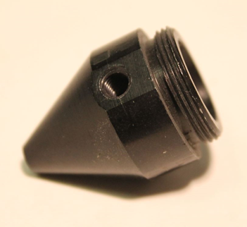 | 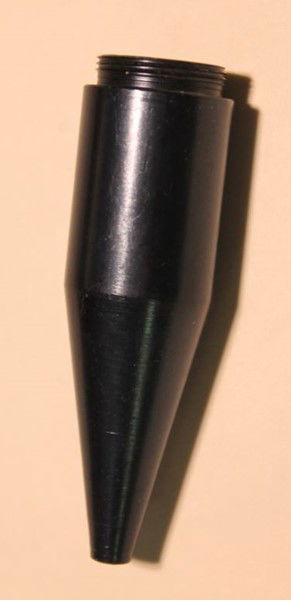 |
| ------------------------------------------------------------------ | -------------------------------------------------------------------- |
| Nozzle for the 50.8mm lens | Nozzle for the 101.6mm lens |
***
## BRM Original
[Section titled “BRM Original”](#brm-original)
### Compatible lenses
[Section titled “Compatible lenses”](#compatible-lenses-1)
* **50.8mm lens** - Detail engraving
* **63.5mm lens** - All-purpose
* **101.6mm lens** - Thick cutting
### Lens shaft configuration
[Section titled “Lens shaft configuration”](#lens-shaft-configuration-1)
**Pink/red lens shaft:**
* Positions on both sides of the shaft
* Rotate shaft 180 degrees to access third lens position
* One shaft accommodates all three lenses
### Important notes
[Section titled “Important notes”](#important-notes)
* Lens must be mounted in correct position for proper focus
* Wrong position causes focus to be above or below material
* Always verify lens orientation (convex side up)
***
## BRM Pro
[Section titled “BRM Pro”](#brm-pro)
### Compatible lenses
[Section titled “Compatible lenses”](#compatible-lenses-2)
* **50.8mm lens** - Detail engraving
* **63.5mm lens** - All-purpose
* **101.6mm lens** - Thick cutting
### Lens shaft configuration
[Section titled “Lens shaft configuration”](#lens-shaft-configuration-2)
**Dedicated lens shafts:**
* Each lens requires its specific lens shaft
* Lens shafts are **not interchangeable**
* Each shaft has a specific position for its lens
### Important notes
[Section titled “Important notes”](#important-notes-1)
* Must use correct shaft for each lens to achieve proper focus
* Cannot use 63.5mm shaft for 50.8mm or 101.6mm lenses
* Switch complete lens shaft assembly when changing lenses
***
## BRM Slim
[Section titled “BRM Slim”](#brm-slim)
### Compatible lenses
[Section titled “Compatible lenses”](#compatible-lenses-3)
* **50.8mm lens** - Detail engraving
* **63.5mm lens** - All-purpose
* **101.6mm lens** - Thick cutting
### Lens shaft configuration
[Section titled “Lens shaft configuration”](#lens-shaft-configuration-3)
**Dedicated lens shafts:**
* Each lens requires its specific lens shaft
* Lens shafts are **not interchangeable**
* Each shaft has a specific position for its lens
### Important notes
[Section titled “Important notes”](#important-notes-2)
* Must use correct shaft for each lens to achieve proper focus
* Cannot use 63.5mm shaft for 50.8mm or 101.6mm lenses
* Switch complete lens shaft assembly when changing lenses
***
## Related articles
[Section titled “Related articles”](#related-articles)
* [Different lenses](/en/general/getting-started/different-lenses) - Compare lens types and their applications
* [Lens assembly](/en/general/getting-started/lens-assembly) - How to install and orient lenses correctly
* [Focus distance for different lenses](/en/general/getting-started/focus-distance-different-lenses) - Determine the correct focus height
**Need help?** [Submit a ticket](/en/contact) with your machine model and lens questions.
# Why you should not laser PVC
> Learn why PVC and chloride-containing materials are dangerous to process with a laser machine, and what happens when you do.
Do not laser PVC or chloride-containing materials
Processing PVC or materials containing chloride/anions with a laser is **extremely dangerous** to your health and will **immediately void your warranty**. BRM Lasers strongly advises against processing these materials under any circumstances.
## What makes PVC dangerous?
[Section titled “What makes PVC dangerous?”](#what-makes-pvc-dangerous)
PVC contains **chloride**, which is a negatively charged ion (anion). When heated by the laser, chloride becomes a toxic gas that actively seeks positive particles to reach a balanced state. This chemical reaction causes severe damage to both your machine and your health.
### Other hazardous anions to avoid
[Section titled “Other hazardous anions to avoid”](#other-hazardous-anions-to-avoid)
PVC is not the only dangerous material. Avoid processing any materials containing these anions:
* **Fluoride (F-)** - Found in fluoropolymers and some plastics
* **Bromide (Br-)** - Found in flame retardants and some vinyl compounds
* **Iodide (I-)** - Found in certain chemical compounds
* **Chloride (Cl-)** - Found in PVC, vinyl, and chlorinated plastics
Not sure about your material?
Request the **MSDS (Material Safety Data Sheet)** from your supplier. This document lists all chemical components. Learn how to read an MSDS in our guide: [What is an MSDS](/en/tips-and-tricks/machines/what-is-a-msds)?
## How the damage happens
[Section titled “How the damage happens”](#how-the-damage-happens)
When you laser PVC or chloride-containing materials, the released gas doesn’t just disappear—it actively attacks everything it touches.
### What happens to your machine
[Section titled “What happens to your machine”](#what-happens-to-your-machine)
The chloride gas pulls positive particles from metal components to balance itself. This process:
* **Corrodes steel parts** - Components appear rusty and turn orange
* **Damages moving parts** - Motors, bearings, and guide wheels deteriorate
* **Creates mechanical play** - The laser head and axes become loose and inaccurate
* **Destroys precision** - Your machine loses accuracy and eventually stops working
The images below show typical damage from chloride exposure:
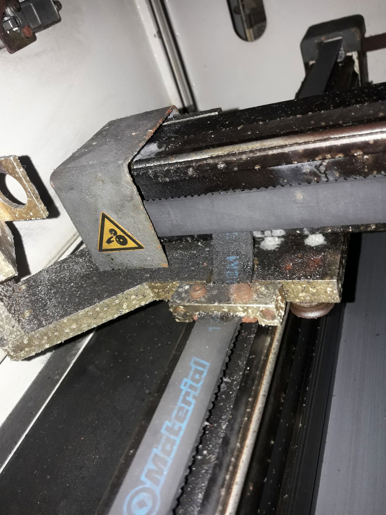
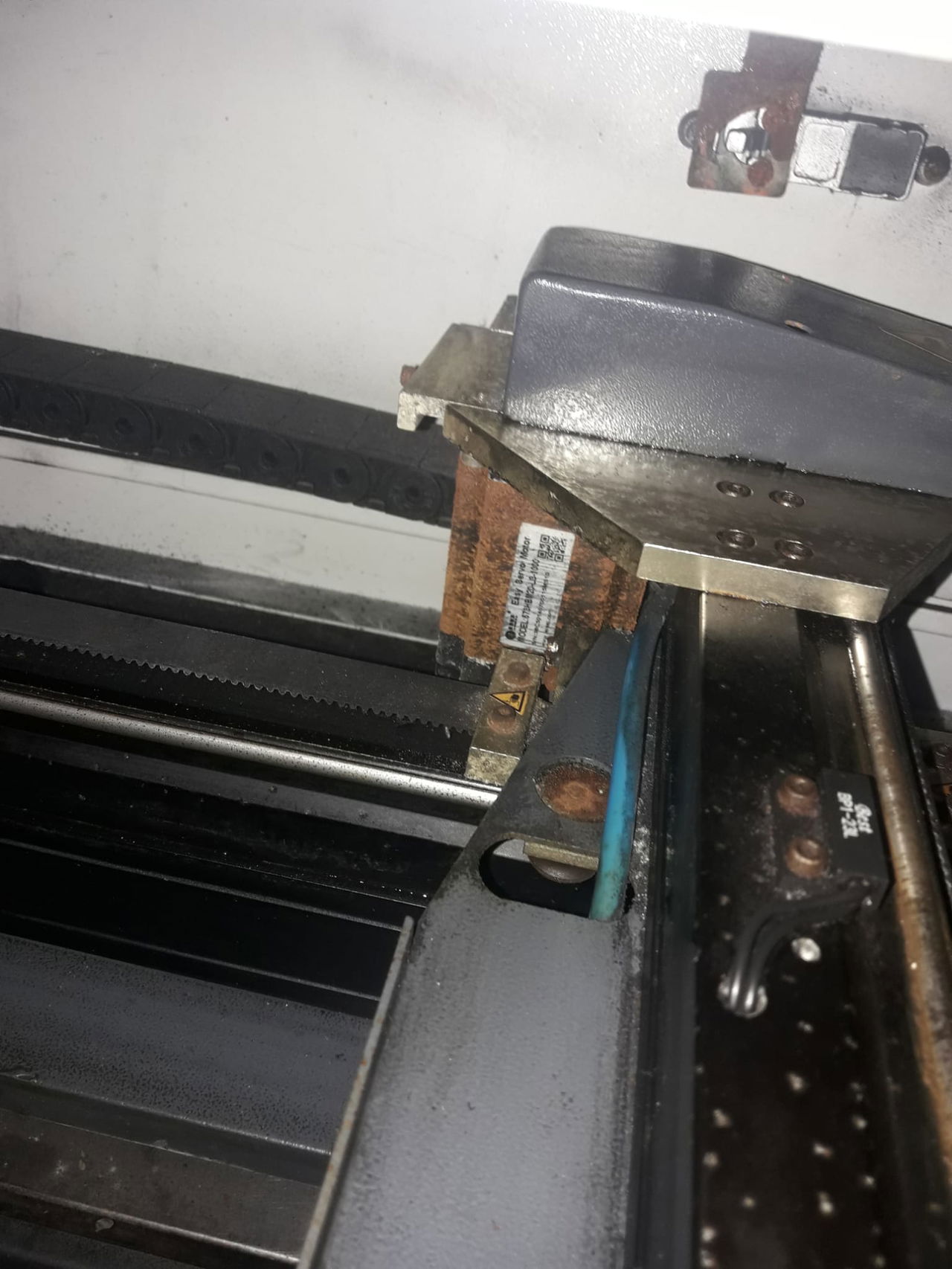
### What happens to your health
[Section titled “What happens to your health”](#what-happens-to-your-health)
Chloride gas is **toxic to humans**. Even with extraction systems, you cannot safely remove these gases. The health effects are severe and include:
* **Immediate effects:** Eye irritation, burning sensation, respiratory discomfort
* **Short-term exposure:** Lung damage, skin irritation
* **Long-term exposure:** Potential blindness, permanent lung damage, increased cancer risk
Extraction systems cannot protect you
Standard extraction systems even with filters cannot safely remove chloride gas. The gas damages the extraction system itself, and filters do not absorb these anions. The “clean” air being exhausted still contains harmful gases.
## What if I accidentally lasered PVC?
[Section titled “What if I accidentally lasered PVC?”](#what-if-i-accidentally-lasered-pvc)
Unfortunately, accidental exposure causes permanent damage. The corrosion process continues until all anions reach chemical balance, which can take **months** after the initial exposure.
### Why the damage continues
[Section titled “Why the damage continues”](#why-the-damage-continues)
Unlike rust (which is self-sustaining), anions stop causing damage once they reach balance. However, you cannot predict when this will happen. The gas particles settle throughout your machine and continue corroding new surfaces they contact.
### Can I repair the damage?
[Section titled “Can I repair the damage?”](#can-i-repair-the-damage)
Replacing individual parts is difficult because:
1. Chloride particles accumulate throughout the machine
2. New parts immediately contact contaminated surfaces
3. The corrosion process transfers to replacement parts
4. It’s impossible to know when all anions have balanced
If you must attempt repairs, follow this decontamination process carefully.
## Emergency decontamination procedure
[Section titled “Emergency decontamination procedure”](#emergency-decontamination-procedure)
Safety first
Wear protective gloves and a proper respirator mask during this entire process. Chloride dust and mist are toxic.
### Step-by-step cleaning
[Section titled “Step-by-step cleaning”](#step-by-step-cleaning)
1. **Wipe down all surfaces** with damp cloths
* Remove every trace of dust and residue
* Pay special attention to corners, crevices, and hidden areas
* The machine must be completely dust-free
2. **Do NOT use vacuum cleaners or compressed air**
* Vacuums lack appropriate filters and will spread anions throughout your workspace
* Compressed air simply displaces the problem
* The vacuum cleaner itself will become contaminated and fail
3. **Dispose of cleaning materials properly**
* Treat all cloths as chemical waste
* Follow local hazardous waste disposal regulations
4. **Wait and observe**
* After cleaning, wait several weeks before replacing parts
* Monitor whether new corrosion appears
* If corrosion stops, the anions may have reached balance
No guarantee of success
Even with thorough decontamination, there is no guarantee your machine will return to normal operation. Chloride damage is often permanent and irreversible.
## Material verification
[Section titled “Material verification”](#material-verification)
**Not sure if your material is safe?** [Submit a ticket](/en/contact) with the material’s MSDS attached. Our team will help you determine if it’s safe to process.
Safe alternatives to PVC
Many PVC-free alternatives exist for common applications:
* Use acrylic instead of PVC sheets
* Choose PVC-free vinyl alternatives
* Request chloride-free materials from your supplier
# Maintenance
### Guidelines
***
[Everything you need to know about the guides of the BRM OriginalEverything you need to know about the guides of the BRM Original](/en/maintenance/guidelines/guidelines-of-the-brm-original)
[>](/en/maintenance/guidelines/guidelines-of-the-brm-original)
### Optical path
***
[Cleaning mirrorsStep by step guide to safely clean your laser machine mirrors and restore optimal beam quality.](/en/maintenance/optical-path/cleaning-mirrors)
[>](/en/maintenance/optical-path/cleaning-mirrors)
[Cleaning the laser sourceCritical safety maintenance to prevent electrical arcing, fire hazards, and maintain laser performance.](/en/maintenance/optical-path/cleaning-the-laser-source)
[>](/en/maintenance/optical-path/cleaning-the-laser-source)
[Lens cleaningComplete guide to safely clean your laser lens and restore optimal cutting performance.](/en/maintenance/optical-path/lens-cleaning)
[>](/en/maintenance/optical-path/lens-cleaning)
[Mirror alignmentStep by step guide to align mirrors for optimal laser beam quality and cutting performance.](/en/maintenance/optical-path/mirror-alignment)
[>](/en/maintenance/optical-path/mirror-alignment)
[Mirror alignment for Open Bed machinesComplete guide to align mirrors on Open Bed laser machines for optimal beam quality and cutting performance.](/en/maintenance/optical-path/mirror-alignment-open-bed)
[>](/en/maintenance/optical-path/mirror-alignment-open-bed)
# Everything you need to know about the guides of the BRM Original
> Everything you need to know about the guides of the BRM Original
Maintenance guide for the [BRM Original](https://www.brmlasers.com/product/pro-1300?utm-source=support-site) linear guideways.
## Linear guideways
[Section titled “Linear guideways”](#linear-guideways)
The [BRM Original](https://www.brmlasers.com/product/pro-1300?utm-source=support-site) has linear guideways. In this case it means it operates with a trolley with guide wheels and not a bearing block.
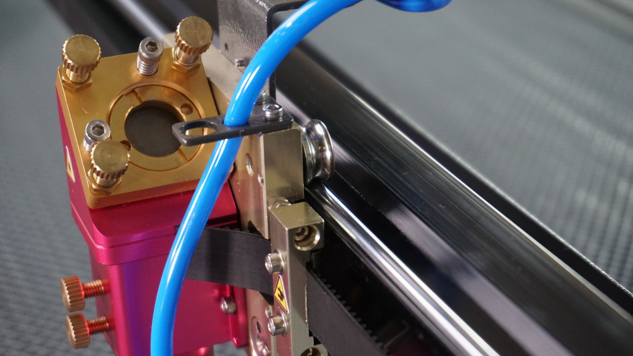
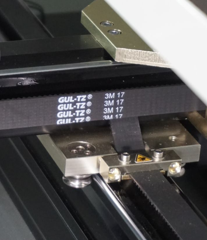
It’s important the linear guideways are and remain in good condition to ensure that the trolleys run well and smoothly. It’s also essential that the guide wheels are well-rounded and do not fit too tightly or too loosely. The linear guideways must be completely intact. There should be no scratches, cracks, grooves or anything else on the linear guideways. They also need to have a polished shine to them and not be dull or stained.
If the linear guideway has scratches, cracks, etc., then so much force has been applied that the linear guideway has been damaged. You can also notice this in the guide wheels. If you feel that the trolley runs smoothly, tightly and smoothly again, then the guide wheels are no longer round but have become somewhat oval. This is therefore a sign that the wheel(s) are broken. If the wheels are no longer round, then they will have to be replaced. If the linear guideways are worn out or broken, they should be renewed as well.
If any of the parts need to be replaced, you can submit a [ticket](/en/contact) on the bottom right of this page to schedule an appointment with a technician.
## Maintaining the linear guideways
[Section titled “Maintaining the linear guideways”](#maintaining-the-linear-guideways)
The linear guideways must be well maintained to ensure that their lifespan will not be shortened. Make sure that the linear guideways are perfectly sound and clean at least once a week. They are not perfectly clean if you can see dust on them or if they are bone-dry. Linear guideways are also not clean when they are no longer in a polished, shiny condition.
If the linear guideways are no longer in good condition, the first thing to do is to clean them. Take a paper towel and wipe the linear guideway completely clean and dry. Lubricate them with a thin film of sewing machine oil. No oil should drip off the linear guideway, there should instead be only a thin film on the linear guideway. Move the laser head from left to right and back again. The same applies to the bridge, moving it from the front to the back and vice versa so the whole length of the linear guideway is covered.
If the linear guideways are filthy after moving them back and forth, the guide wheels will be filthy too. When this happens, put a thin piece of paper on the linear guideway. Move the head or bridge over the paper so it will absorb the dirt. Once the paper has absorbed the dirt, re-oil the linear guideways with a thin layer of sewing machine oil.
You can use a low-viscosity oil with good adhesion if you do not have any sewing machine oil. A high-speed oil will also do just fine. If you use the wrong oil the performance of the machine will decline. Also, if you use high viscosity oil or grease, you will experience resistance from the oil / grease. It can even be that when you use grease, it will absorb the dirt. If that occurs, you will have to lubricate 3 or 4 times a week because the whole area will quickly become very dirty.
Please submit a [ticket](/en/contact) if you are unable to solve the problem and we will help you.
# Cleaning mirrors
> Step by step guide to safely clean your laser machine mirrors and restore optimal beam quality.
Dirty mirrors reduce laser power and cutting quality. Regular cleaning maintains optimal performance. Clean mirrors when you notice power loss, poor cutting results, or visible dirt on the mirror surface.
## Required materials
[Section titled “Required materials”](#required-materials)
* Latex or nitrile gloves
* Clean cotton cloth (lint free)
* 70% isopropyl alcohol
* Flashlight (for inspection)
* Flathead screwdriver
* Allen key set
Use only approved materials
Mirror and lens surfaces are extremely sensitive. Using incorrect cleaning materials will permanently damage the optical coating. Only use 70% alcohol and lint-free cotton cloths.
## Safety preparation
[Section titled “Safety preparation”](#safety-preparation)
**Before you begin:**
1. **Turn off the laser machine** completely
2. **Inspect the cotton cloth** for particles or debris that could scratch
3. **Put on latex gloves** to prevent fingerprints and oils on the optics
## Removing mirrors
[Section titled “Removing mirrors”](#removing-mirrors)
### Mirror 1 (near laser source)
[Section titled “Mirror 1 (near laser source)”](#mirror-1-near-laser-source)
**BRM Pro:**
* Mirror is covered by a metal plate
* Remove 2 Allen bolts with Allen key
* Carefully remove the metal plate
**Other models (Budget, Original, Slim):**
* Mirror is covered by a threaded ring
* Unscrew the ring by hand
### Mirror 2 (on BRM Pro only)
[Section titled “Mirror 2 (on BRM Pro only)”](#mirror-2-on-brm-pro-only)
Same procedure as Mirror 1 above.
### Mirror 3 (on laser head, all models)
[Section titled “Mirror 3 (on laser head, all models)”](#mirror-3-on-laser-head-all-models)
The mirror on the laser head has a threaded retention ring:
1. Try unscrewing by hand first
2. If too tight, use a flathead screwdriver in the ring slots
3. Apply gentle, steady pressure to loosen
4. **Important:** Do not let the screwdriver slip and contact the mirror surface
Once the ring is loose, carefully lift the mirror from its holder.
## Cleaning procedure
[Section titled “Cleaning procedure”](#cleaning-procedure)
Follow these steps for each mirror:
1. **Wet the cotton cloth** with 70% alcohol (not dripping wet, just damp)
2. **Hold the mirror by its edges** (never touch the reflective surface with bare fingers)
3. **Gently wipe the mirror** in one direction across the surface
* Use light pressure
* Do not scrub or apply force
* Let the alcohol do the work
4. **Dry with clean cotton cloth** to prevent alcohol stains
* Use a fresh, dry section of cloth
* Wipe gently until completely dry
* No streaks or residue should remain
5. **Inspect with flashlight** to verify the mirror is completely clean
## Reinstalling mirrors
[Section titled “Reinstalling mirrors”](#reinstalling-mirrors)
**Critical: Check mirror orientation**
The reflective (shiny) side must face toward the laser beam path. Installing backwards will prevent the laser from working.
### Installation steps
[Section titled “Installation steps”](#installation-steps)
1. **Place mirror in holder** with reflective side facing the correct direction
* Mirror 1: Reflective side toward laser source
* Mirror 2: Reflective side toward Mirror 1
* Mirror 3: Reflective side toward the lens
2. **Replace the cover or ring**
* Pro: Align metal plate and insert Allen bolts
* Other models: Thread ring by hand first
3. **Tighten securely but gently**
* The ring/cover should be snug
* Do not over-tighten (this can stress the mirror and cause damage)
* The mirror should not flex or show tension
## After cleaning
[Section titled “After cleaning”](#after-cleaning)
Check mirror alignment
After cleaning and reinstalling mirrors, your mirror alignment may have shifted. Always verify and adjust alignment after mirror maintenance. See: [Mirror alignment guide](/en/maintenance/optical-path/mirror-alignment)
## Cleaning schedule
[Section titled “Cleaning schedule”](#cleaning-schedule)
* **Light use (education):** Clean every 3 months or when power drops
* **Medium use (creative):** Clean monthly
* **Heavy use (production):** Clean weekly or when power drops
**Signs you need to clean:**
* Visible dirt or residue on mirror surface
* Reduced cutting power
* Poor edge quality
* Inconsistent engraving depth
# Cleaning the laser source
> Critical safety maintenance to prevent electrical arcing, fire hazards, and maintain laser performance.
Dust and dirt on your laser source exterior conduct electricity and create serious safety hazards. Regular cleaning prevents electrical arcing, fire risk, and maintains laser performance.
High voltage is lethal
Only qualified technicians may perform laser source maintenance. Turn off the machine, unplug it, and wait at least 24 hours before cleaning to ensure the source is fully discharged.
## Why cleaning is critical
[Section titled “Why cleaning is critical”](#why-cleaning-is-critical)
Dust and dirt on the laser source conduct electricity. Instead of flowing through the laser source to create a beam, electricity can arc across the dirty exterior from plus to minus. This creates:
* **Fire hazard** at the laser source
* **Electrocution risk** for operators
* **No laser beam** (power flows outside instead of through the source)
* **Reduced performance** and premature failure
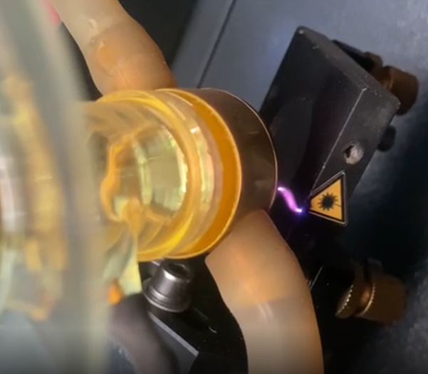
## How often to clean
[Section titled “How often to clean”](#how-often-to-clean)
Cleaning frequency depends on:
* Materials you process (wood creates more visible dust)
* How often you use the machine
* Workshop environment (dust levels)
**Establish your cleaning schedule:**
1. **Start with 2 week intervals** for the first cleaning
2. **Clean only half the source** (e.g., front half) to compare
3. **After 2 weeks, inspect:**
* Heavy buildup = clean weekly
* Light buildup = clean monthly
4. **Adjust schedule** based on your specific conditions
Wood vs acrylic
Wood processing creates more visible dust than transparent acrylic, but both materials leave residue that conducts electricity. Clean regularly regardless of visibility.
## Required materials
[Section titled “Required materials”](#required-materials)
* Latex or nitrile gloves (required)
* Lint-free cleaning paper or paper towels
* 70% isopropyl alcohol in spray bottle
* Allen key set (to access laser source)
## Safety preparation
[Section titled “Safety preparation”](#safety-preparation)
**Before you begin:**
1. **Turn off the laser machine** completely
2. **Unplug the machine** from power
3. **Wait at least 24 hours** for the laser source to fully discharge
24 hour waiting period is mandatory
High voltage capacitors in the laser source retain lethal voltage even after the machine is turned off. The 24 hour waiting period ensures complete discharge. Working on the source before this can result in electrocution.
4. **Put on gloves** before touching the laser source
**Why gloves are required:** Fingerprints contain oils that conduct electricity. Fingerprints on the laser source create conductive paths for electricity to arc along, creating a dangerous situation.
## Cleaning procedure
[Section titled “Cleaning procedure”](#cleaning-procedure)
### Step 1: Remove loose dust
[Section titled “Step 1: Remove loose dust”](#step-1-remove-loose-dust)
1. **Put on latex gloves**
2. **Use dry cleaning paper** to gently remove loose dust from the laser source exterior
3. **Work carefully** around electrical connections and glass components
### Step 2: Deep clean with alcohol
[Section titled “Step 2: Deep clean with alcohol”](#step-2-deep-clean-with-alcohol)
1. **Spray alcohol** on the laser source exterior
2. **Wipe with dry cleaning paper** to remove all remaining dust and residue
3. **Check all surfaces** are completely clean
### Step 3: Final alcohol treatment
[Section titled “Step 3: Final alcohol treatment”](#step-3-final-alcohol-treatment)
1. **Spray alcohol** on the laser source once more
2. **Let alcohol air dry** (do not wipe)
3. **Inspect for fingerprints** and ensure none are visible
No fingerprints
The final alcohol spray should air dry without wiping. This ensures no oils or fingerprints remain on the surface. Any conductive residue creates an electrical arc path and safety hazard.
## While you’re there: Additional checks
[Section titled “While you’re there: Additional checks”](#while-youre-there-additional-checks)
Since you have the laser source accessible, perform these additional inspections:
### Check the output lens
[Section titled “Check the output lens”](#check-the-output-lens)
At the front of the laser source (tapered end), there is a lens. Inspect it while the machine is unplugged and discharged.
**Healthy lens:**
* Evenly colored coating
* Clear and transparent
* No cracks or damage
**Problem signs:**
* Uneven coloring
* Cloudy or opaque
* Cracks or chips
If you notice any damage, take a photo and [submit a ticket](/en/contact) for guidance.
### Check water connections
[Section titled “Check water connections”](#check-water-connections)
1. **Verify water hoses** are securely attached to the laser source
2. **Inspect cooling water** inside the source through the glass tube
3. **Look for algae or dirt** in the cooling water
Contaminated cooling water
If you see algae or dirt in the cooling water, the water needs to be replaced. Contaminated water reduces cooling efficiency and can damage the laser source. See: [Water chiller maintenance](/en/peripherals/water-chiller/the-water-chiller-in-top-condition)
### Check the cathode condition
[Section titled “Check the cathode condition”](#check-the-cathode-condition)
The cathode is a metal shaft visible inside the tapered end of the laser source. It indicates laser source wear.
**Cathode condition guide:**
| 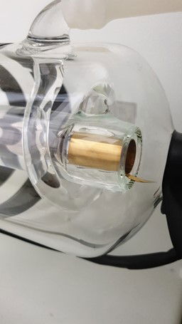 | 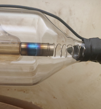 |
| -------------------------------------------------------------------------------------- | ------------------------------------------------------------------------------- |
| **Healthy:** Even brass or silver color (new source) | **Worn:** Dark discoloration (well-used source) |
**If the cathode is discolored AND you’re experiencing power loss:**
This indicates the laser source is degrading and may need replacement soon. [Submit a ticket](/en/contact) to assess whether a technician visit is needed.
## After cleaning
[Section titled “After cleaning”](#after-cleaning)
Once cleaning and inspections are complete:
1. **Reassemble any covers** or panels
2. **Document the date** for maintenance records
3. **Plug the machine back in** and resume normal operation
## Cleaning schedule
[Section titled “Cleaning schedule”](#cleaning-schedule)
* **Heavy use (production):** Check every 2 weeks, clean as needed
* **Medium use (creative):** Clean monthly
* **Light use (education):** Clean every 2 to 3 months
**Adjust based on dust buildup in your specific environment.**
## Related articles
[Section titled “Related articles”](#related-articles)
* [Cleaning mirrors](/en/maintenance/optical-path/cleaning-mirrors)
* [Lens cleaning](/en/maintenance/optical-path/lens-cleaning)
* [Water chiller maintenance](/en/peripherals/water-chiller/the-water-chiller-in-top-condition)
# Lens cleaning
> Complete guide to safely clean your laser lens and restore optimal cutting performance.
A dirty lens reduces laser power and causes poor cutting quality. Regular lens cleaning maintains optimal performance and extends lens life. Clean your lens when you notice reduced power, inconsistent cuts, or visible residue on the lens surface.
Handle with extreme care
The lens has a specialized optical coating that is easily damaged. Always wear gloves, use only 70% alcohol, and handle the lens by its edges only. Never touch the lens surfaces with bare hands.
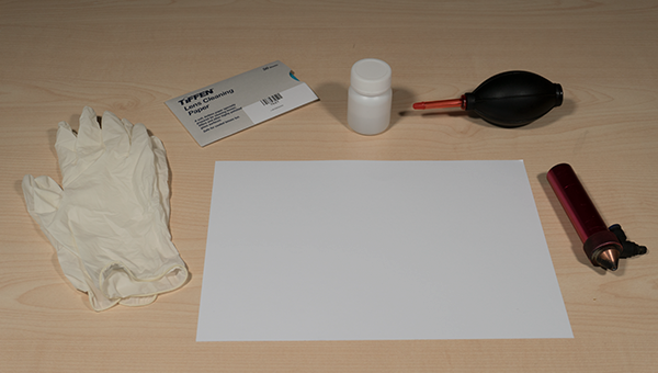
## Required materials
[Section titled “Required materials”](#required-materials)
* Clean workspace with good lighting
* Lens paper (specialized optical paper)
* 70% isopropyl alcohol
* Hand air pump blower
* Latex or nitrile gloves
* Flathead screwdriver (small)
* Clean white paper (to work on)
**Prepare your workspace:** Make sure the area is clean and dust free so the lens does not get contaminated during cleaning.
## Step 1: Remove the lens shaft from laser head
[Section titled “Step 1: Remove the lens shaft from laser head”](#step-1-remove-the-lens-shaft-from-laser-head)
The lens is located inside the lens shaft, which sits in the laser head. You need to remove the entire lens shaft first.
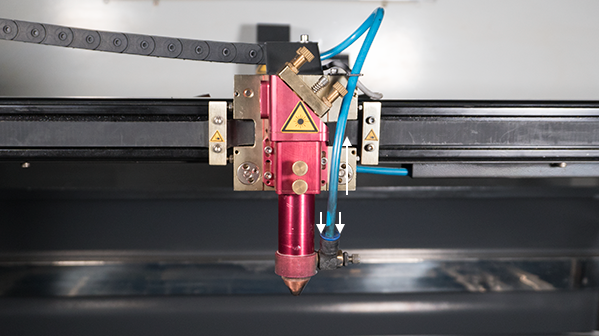
### Disconnect air hose and autofocus sensor
[Section titled “Disconnect air hose and autofocus sensor”](#disconnect-air-hose-and-autofocus-sensor)
1. **Remove air hose:** Push down the blue ring on the air coupling and pull up the hose
2. **Disconnect autofocus sensor** (if equipped):
* Locate the black plug with silver ring at the top of the sensor
* Twist the silver ring counterclockwise
* Pull the plug straight up and out
### Remove lens shaft
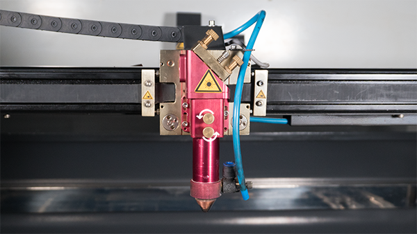
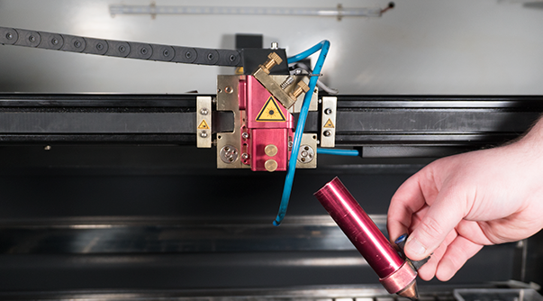
[Section titled “Remove lens shaft”](#remove-lens-shaft)
3. **Loosen fixation bolt(s)** on the laser head by turning counterclockwise
4. **Carefully remove the lens shaft** from the laser head
## Step 2: Disassemble the lens shaft
[Section titled “Step 2: Disassemble the lens shaft”](#step-2-disassemble-the-lens-shaft)
Take the lens shaft to your clean workstation.
1. **Remove nozzle and nozzle mount** by unscrewing, set aside
2. **Note the lens position:** If your lens shaft has multiple threaded positions (top and bottom), remember which position the lens is in. You must reinstall it in the exact same position.
3. **Put on latex gloves** to protect the lens coating from oils and fingerprints
### Extract the lens
[Section titled “Extract the lens”](#extract-the-lens)
4. **Loosen the lens fixation ring** using a small flathead screwdriver:
* Insert screwdriver tip into one of the small notches in the ring
* Apply gentle pressure and rotate counterclockwise
* Be careful the screwdriver does not slip and damage the lens
* Once loose, continue unscrewing by hand
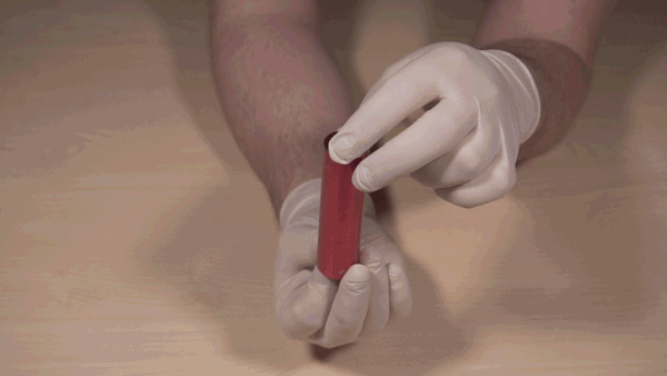
5. **Hold the lens shaft carefully:**
* Hold the shaft at the top
* Let the lens fixation ring, white lens ring, and lens sit at the bottom
* Carefully unscrew the fixation ring completely
* **Do not drop the lens** (it is fragile and will break if dropped)
## Step 3: Clean the lens
[Section titled “Step 3: Clean the lens”](#step-3-clean-the-lens)
Set aside the lens fixation ring and white lens ring. Hold the lens carefully by its edges only.
### Remove loose dirt
[Section titled “Remove loose dirt”](#remove-loose-dirt)
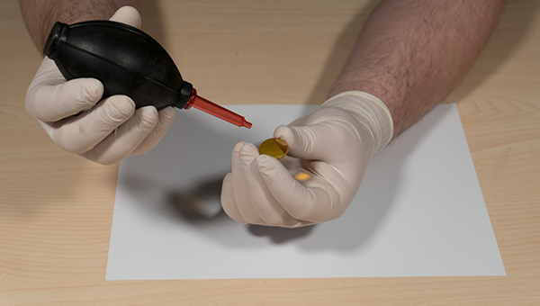
1. **Use the hand air pump blower** to remove loose dust and particles
* Hold the pump at an angle to the lens surface
* Blow air across the lens, not directly into it
* This prevents particles from scratching during wet cleaning
### Wet cleaning process
[Section titled “Wet cleaning process”](#wet-cleaning-process)
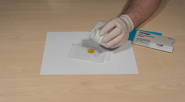
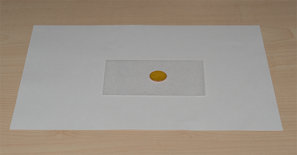
2. **Prepare the lens paper sandwich:**
* Place one sheet of lens paper on your clean white paper
* Place the lens on top of the lens paper
* Place another sheet of lens paper on top of the lens
3. **Apply alcohol:**
* Add 1 to 2 drops of 70% isopropyl alcohol to the top lens paper
* The lens paper should be damp, not soaking wet
Use only 70% alcohol
Using any other cleaning product will permanently damage or remove the optical coating. A damaged coating cannot be repaired. The lens must be replaced.
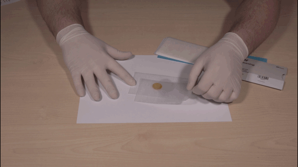
4. **Wipe the lens clean:**
* Gently pull the top sheet of lens paper across the lens in one smooth motion
* Do not scrub or apply pressure
* The lens paper will lift dirt and dry the surface simultaneously
5. **Clean the other side:**
* Flip the lens over
* Repeat steps 2 through 4 for the other side
* Inspect both sides to ensure they are completely clean with no streaks or residue
## Step 4: Reassemble the lens
[Section titled “Step 4: Reassemble the lens”](#step-4-reassemble-the-lens)
Once the lens is completely clean and dry, reassemble the lens assembly.
### Critical: Check lens orientation
[Section titled “Critical: Check lens orientation”](#critical-check-lens-orientation)
**The convex (curved) side must face UP toward the mirror.** Installing the lens backwards will cause:
* Incorrect focus height
* Poor cutting quality
* Thick, unfocused beam
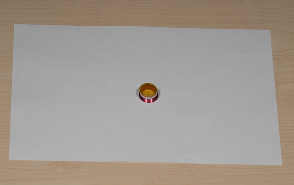
### Assembly order (from bottom to top):
[Section titled “Assembly order (from bottom to top):”](#assembly-order-from-bottom-to-top)
1. Lens fixation ring (threads facing up)
2. White lens ring
3. Lens with convex side facing UP
4. This assembly screws into the lens shaft
Remember the position
Install the lens in the exact same position in the lens shaft where you removed it from. Wrong position = wrong focus height.
## Step 5: Install lens shaft back into laser head
[Section titled “Step 5: Install lens shaft back into laser head”](#step-5-install-lens-shaft-back-into-laser-head)
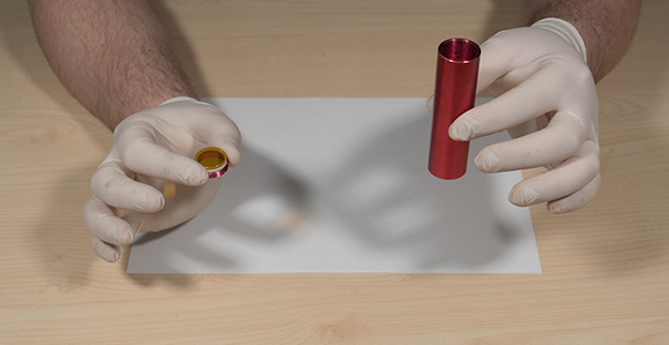
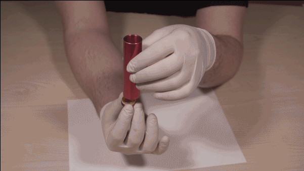
1. **Screw the lens assembly into the lens shaft** from below
* Hold the lens shaft in one hand
* Hold the lens assembly (fixation ring, white ring, lens) in the other
* Carefully thread the fixation ring into the lens shaft
* Tighten snugly but do not over-tighten
2. **Reattach nozzle and nozzle mount** to the lens shaft
3. **Insert lens shaft into laser head**
* Align the shaft with the mounting hole
* Push firmly until fully seated
4. **Tighten fixation bolt(s)** on the laser head by turning clockwise
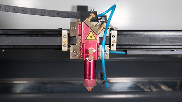
### Reconnect air hose and autofocus
[Section titled “Reconnect air hose and autofocus”](#reconnect-air-hose-and-autofocus)
5. **Reinsert air hose** into the air coupling
* Push the hose into the coupling until you hear a click
* Gently pull to verify it is locked in place
6. **Reconnect autofocus sensor** (if equipped):
* Locate the small alignment pin inside the plug
* Align the pin with the hole in the sensor (only fits one way)
* Push the plug straight down into the sensor
* Twist the silver ring clockwise to lock
Do not force the autofocus plug
The plug has a small pin that must align with a hole in the sensor. Forcing the plug in the wrong orientation will break the pin, requiring replacement of the entire cable assembly. Take your time and ensure proper alignment.
## After cleaning
[Section titled “After cleaning”](#after-cleaning)
Your machine is now ready to operate. Test with a small job to verify proper focus and cutting quality.
**Need help?** [Submit a ticket](/en/contact) if you experience issues after cleaning.
## Cleaning schedule
[Section titled “Cleaning schedule”](#cleaning-schedule)
* **Light use (education):** Clean every 2 to 3 months
* **Medium use (creative):** Clean monthly
* **Heavy use (production):** Clean weekly or when power drops
**Signs you need to clean:**
* Reduced cutting power
* Inconsistent engraving depth
* Poor edge quality
* Visible smoke residue or dirt on lens surface
# Mirror alignment
> Step by step guide to align mirrors for optimal laser beam quality and cutting performance.
Your laser beam travels from the source through mirrors to the lens, then to your material. Proper mirror alignment ensures the beam hits the center of each mirror and lens, maximizing power and cut quality.
**Clean first, then align.** Dirty optics reduce power and affect beam position. Always [clean mirrors](/en/maintenance/optical-path/cleaning-mirrors) and [clean the lens](/en/maintenance/optical-path/lens-cleaning) before adjusting alignment.
When to check alignment
* Reduced cutting power
* Inconsistent results across the work area
* Shadow line or double cutting line appears
* After cleaning or replacing mirrors
* After moving or servicing the machine
## Before you start
[Section titled “Before you start”](#before-you-start)
**Check your laser head type.** The mirror adjustment pattern varies by model:
* **Budget and Original:** Standard adjustment pattern (2 bolts used)
* **Slim and Pro:** Different adjustment pattern (all 3 bolts used)
See photos below the video for the specific pattern on Slim and Pro models.
## Video instruction
[Section titled “Video instruction”](#video-instruction)
This video shows the complete mirror alignment process step by step:
### Slim and Pro laser head adjustment
[Section titled “Slim and Pro laser head adjustment”](#slim-and-pro-laser-head-adjustment)
On Slim and Pro models, the adjustment bolt pattern is different. You must use all 3 adjustment bolts to properly align the mirror on the laser head:
| 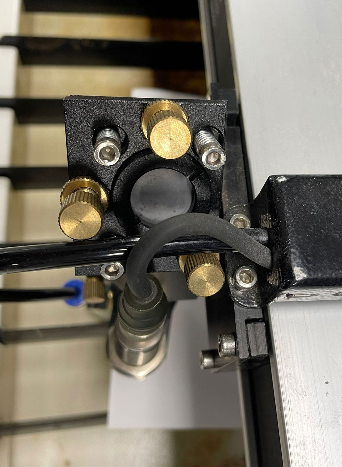 | 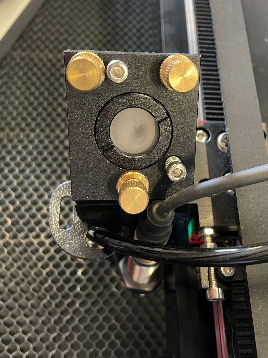 |
| ---------------------------------------------------------------- | ------------------------------------------------------------------- |
| Pro laser head adjustment pattern | Slim laser head adjustment pattern |
## Related articles
[Section titled “Related articles”](#related-articles)
* [Cleaning mirrors](/en/maintenance/optical-path/cleaning-mirrors)
* [Lens cleaning](/en/maintenance/optical-path/lens-cleaning)
* [Mirror alignment for Open Bed machines](/en/maintenance/optical-path/mirror-alignment-open-bed)
* [Double cutting line troubleshooting](/en/problems-and-solutions/co2-machines/help-there-is-a-double-line-in-my-cutting-and-engraving-work)
# Mirror alignment for Open Bed machines
> Complete guide to align mirrors on Open Bed laser machines for optimal beam quality and cutting performance.
Your Open Bed laser beam travels from the source through mirrors to the lens, then to your material. Proper mirror alignment ensures the beam hits the center of each mirror and lens across the entire work area, maximizing power and cut quality.
**Clean first, then align.** Dirty optics reduce power and affect beam position. Always [clean mirrors](/en/maintenance/optical-path/cleaning-mirrors) and [clean the lens](/en/maintenance/optical-path/lens-cleaning) before adjusting alignment.
When to check alignment
* Reduced cutting power
* Inconsistent results across the work area
* Shadow line or double cutting line appears
* After cleaning or replacing mirrors
* After moving or servicing the machine
## Required materials
[Section titled “Required materials”](#required-materials)
* Masking tape (multiple pieces)
* Allen key set
* Wrench set (for adjustment nuts)
* Pen and ruler
* Patience (alignment takes time and precision)
## Step 1: Align Mirror 1 (first mirror on bridge)
[Section titled “Step 1: Align Mirror 1 (first mirror on bridge)”](#step-1-align-mirror-1-first-mirror-on-bridge)
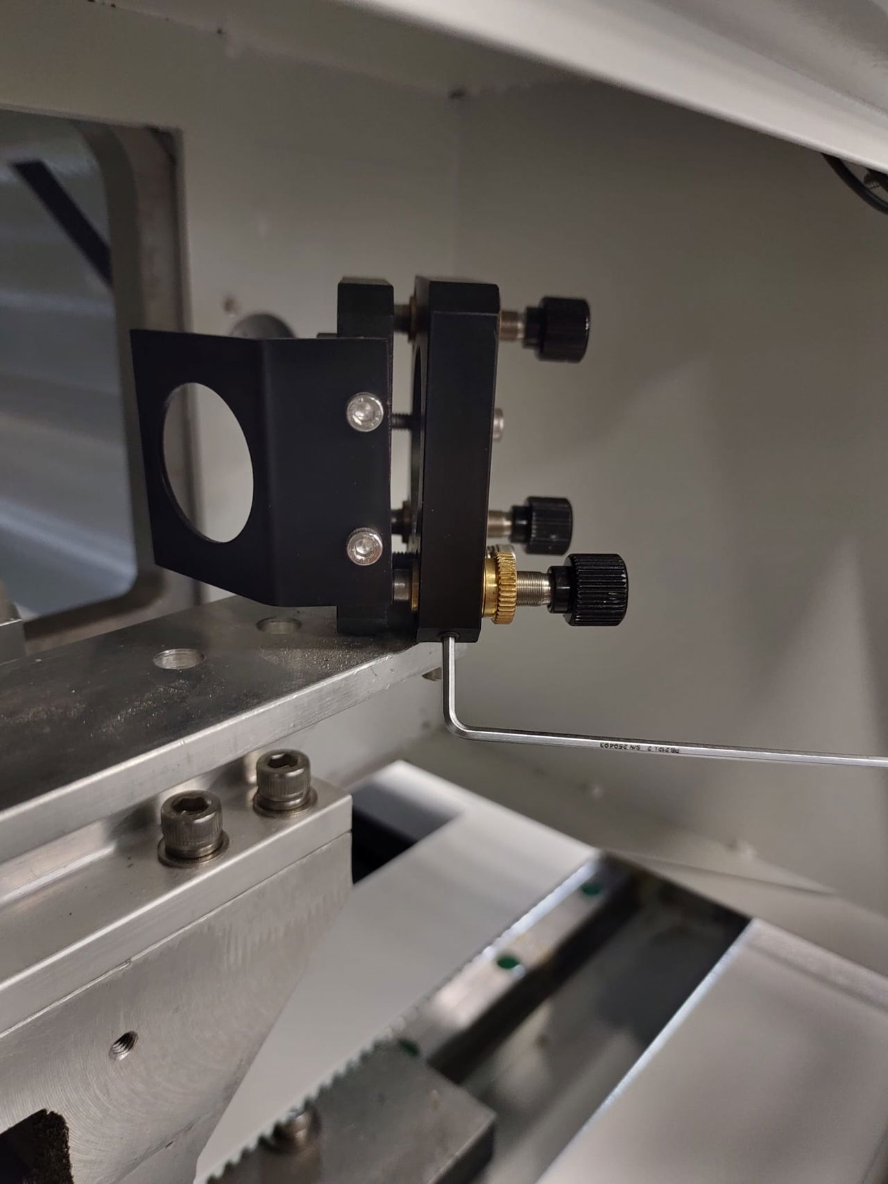
### Check fixation bolts
[Section titled “Check fixation bolts”](#check-fixation-bolts)
1. Open the door on the left side of the bridge
2. Locate the two black mirror holders inside
3. Use an Allen key to check the small socket screws on the holders are tight
4. Tighten any loose screws (these secure the adjustment bolts and nuts)
### Test Mirror 1 alignment
[Section titled “Test Mirror 1 alignment”](#test-mirror-1-alignment)
1. **Prepare tape target:** Tape two pieces of masking tape together
2. **Attach to opening:** Stick tape to the opening on the right mirror holder
3. **Close door** and set a pulse
4. **Check position:** The pulse should be centered in the opening
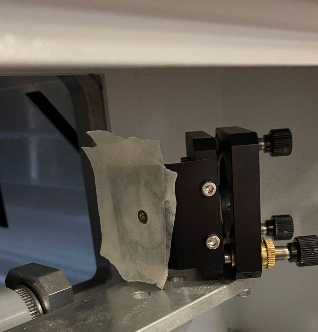
### Adjust Mirror 1 if needed
[Section titled “Adjust Mirror 1 if needed”](#adjust-mirror-1-if-needed)
If the pulse is not centered, adjust the left mirror (first mirror):
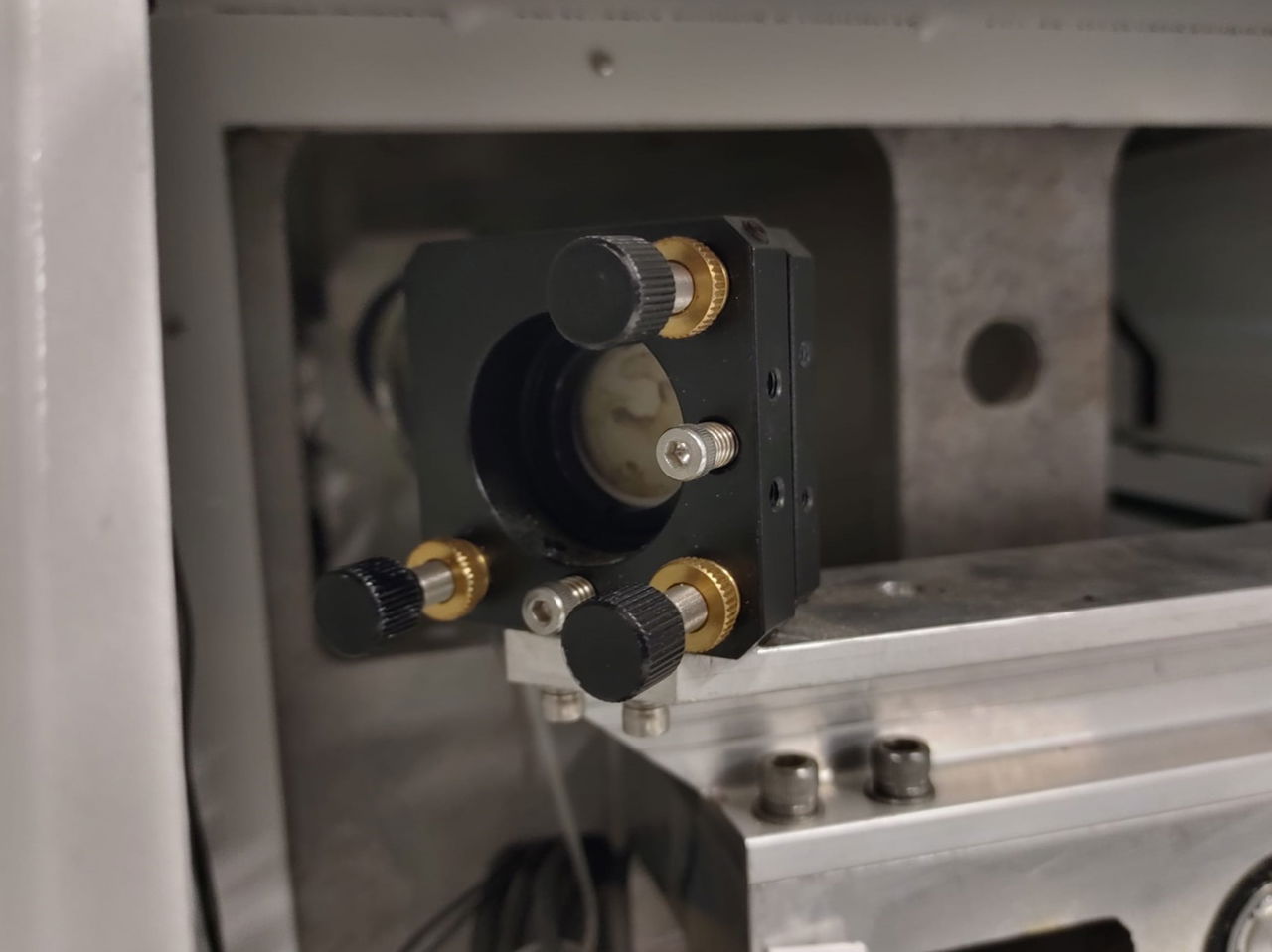
**Adjustment bolts you use:**
* **Top right bolt:** Adjusts beam height (up/down)
* **Bottom left bolt:** Adjusts beam position (left/right)
**Do NOT use:**
* Bottom right adjustment bolt
* Allen bolts (these are for fixation only)
**Adjustment procedure:**
1. **Loosen locking nut** slightly on the bolt you need to adjust
2. **Turn adjustment bolt** to move the beam
3. **Tighten locking nut** when done
4. **Set a new pulse** to verify (bolt may shift when tightening)
5. **Move top tape layer** before each new pulse so you can see the new mark clearly
6. Repeat until pulse is centered
When the pulse hits the center, remove the tape and close the door.
## Step 2: Align Mirror 2 (second mirror on bridge)
[Section titled “Step 2: Align Mirror 2 (second mirror on bridge)”](#step-2-align-mirror-2-second-mirror-on-bridge)
### Test alignment across work area
[Section titled “Test alignment across work area”](#test-alignment-across-work-area)
1. **Open front cover** to access the laser head
2. **Stick 2 layers of masking tape** on the left side opening of the laser head
3. **Close front cover**
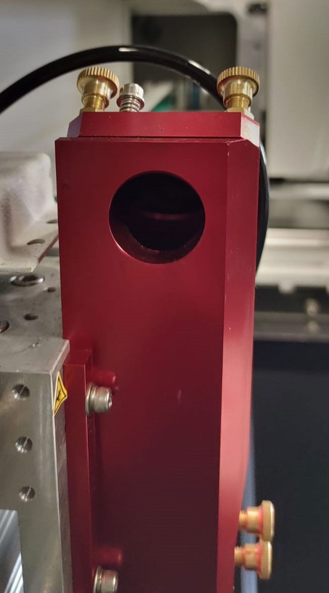
4. **Move laser head to far left** of the work area
5. **Set a pulse**
6. **Move laser head to far right** of the work area
7. **Open front cover** and stick a third piece of tape over the existing tape
8. **Close front cover** and **set a pulse**
### Check the results
[Section titled “Check the results”](#check-the-results)
Compare the two pulses on the tape:
* **Ideal:** Both pulses overlap exactly and are centered in the opening
* **Needs adjustment:** Pulses are not overlapping or not centered
### Adjust Mirror 2 if needed
[Section titled “Adjust Mirror 2 if needed”](#adjust-mirror-2-if-needed)
If alignment is off, adjust the second mirror (right mirror behind the door):
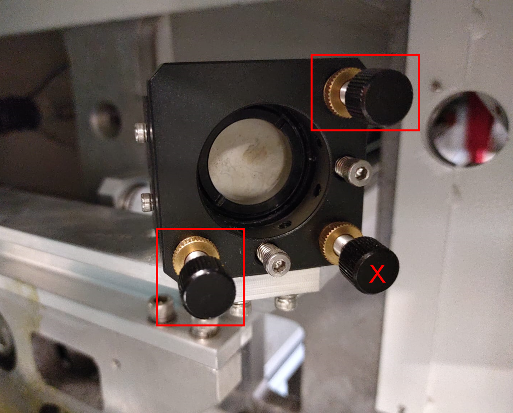
**Adjustment bolts you use:**
* **Top right bolt:** Adjusts beam height (up/down)
* **Bottom left bolt:** Adjusts beam position (left/right)
**Do NOT use:**
* Bottom right adjustment bolt
* Allen bolts (these are for fixation only)
**Adjustment procedure:**
1. **Loosen locking nut** slightly on the bolt you need to adjust
2. **Turn adjustment bolt** to move the beam
3. **Tighten locking nut** when done
4. **Set new pulses** following the test procedure above
5. **Move top tape layer** before each test so you can see new marks
6. Repeat until both pulses overlap and are centered
When pulses are aligned, remove the tape.
## Step 3: Align Mirror 3 (mirror on laser head)
[Section titled “Step 3: Align Mirror 3 (mirror on laser head)”](#step-3-align-mirror-3-mirror-on-laser-head)
### Prepare the lens shaft for testing
[Section titled “Prepare the lens shaft for testing”](#prepare-the-lens-shaft-for-testing)
1. **Remove lens shaft** from the laser head
2. **Unscrew the two parts** of the lens shaft from each other
3. **Set aside the lower part** (you won’t need it yet)
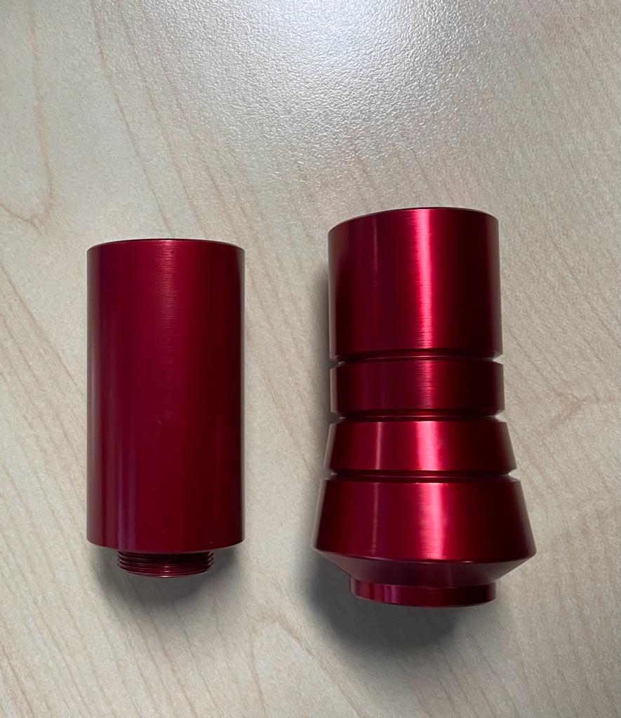
4. **Stick transparent tape** on the threaded bottom of the upper part to cover the opening
5. **Place upper part back** in the laser head as high as possible
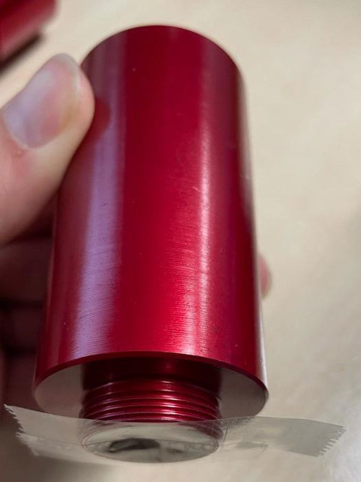
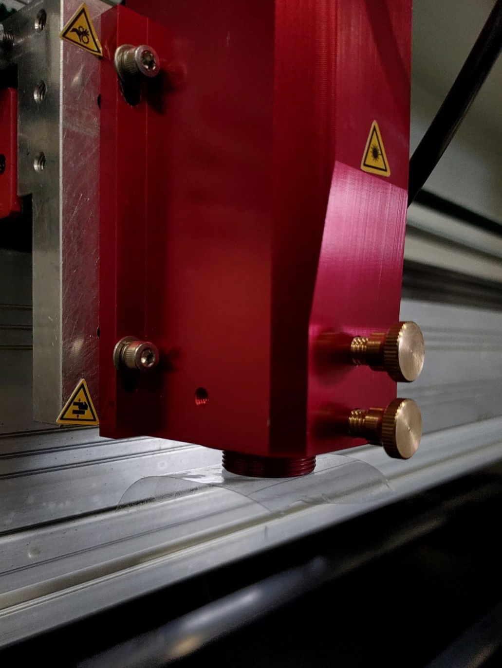
### Test Mirror 3 alignment
[Section titled “Test Mirror 3 alignment”](#test-mirror-3-alignment)
1. **Close front cover** and set 2 pulses
2. **Lower the lens shaft straight down** (do not rotate it)
3. **Secure at lowest position**
4. **Stick masking tape crosswise** over the clear tape
5. **Set a pulse**
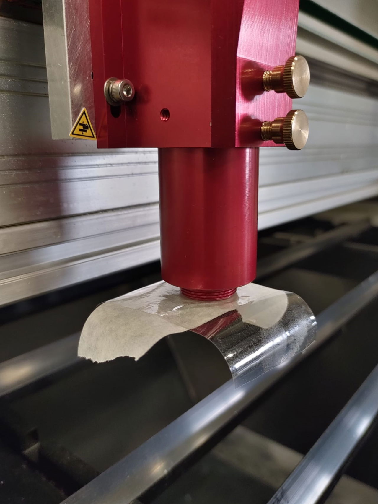
Mark the tape orientation
Before removing the tape, mark which side is left, right, top, and bottom. Without these marks, you won’t know which direction to adjust the mirror if it’s misaligned.
### Check alignment
[Section titled “Check alignment”](#check-alignment)
1. **Remove both tape layers together** (keep them stuck together)
2. **Inspect the burn mark** on the masking tape
3. **Check position:** The burn should be centered in the large hole of the clear tape
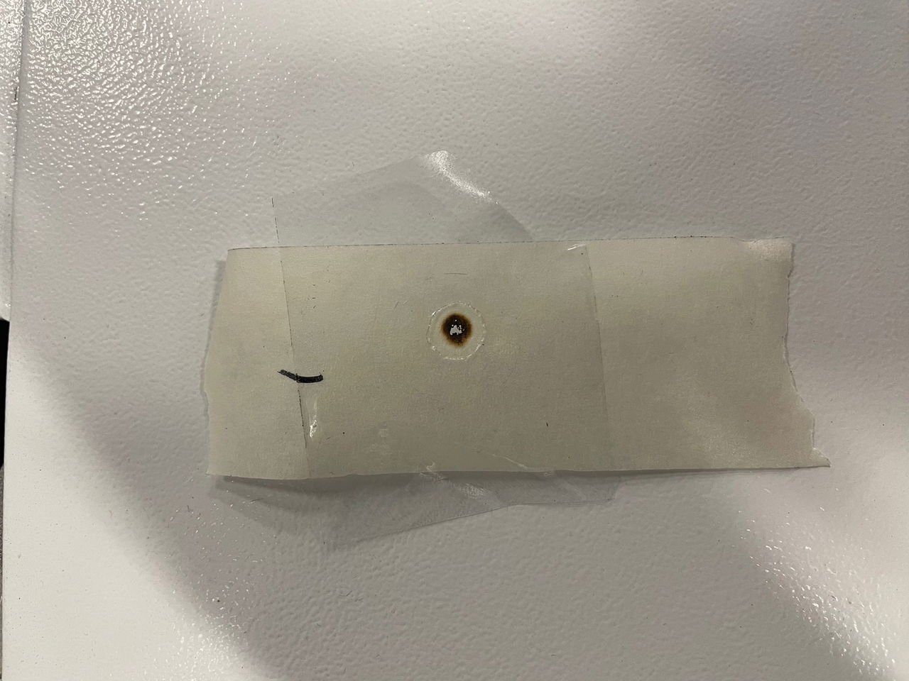
### Adjust Mirror 3 if needed
[Section titled “Adjust Mirror 3 if needed”](#adjust-mirror-3-if-needed)
If the burn is not centered, adjust the laser head mirror:
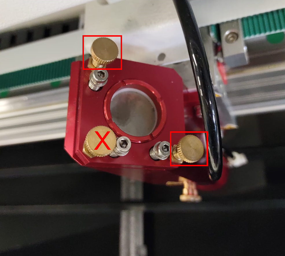
**Adjustment bolts you use:**
* **Top left bolt:** Adjusts beam height (up/down)
* **Bottom right bolt:** Adjusts beam position (left/right)
**Do NOT use:**
* Bottom left adjustment bolt
* Silver Allen bolts (these are for fixation only)
**Adjustment procedure:**
1. **Loosen locking nut** slightly on the bolt you need to adjust
2. **Turn adjustment bolt** to move the beam (use your tape marks to know which direction)
3. **Tighten locking nut** when done
4. **Repeat the entire test** (bolt may shift when tightening)
5. Continue until burn is centered
## Step 4: Align laser source (final alignment)
[Section titled “Step 4: Align laser source (final alignment)”](#step-4-align-laser-source-final-alignment)
After all mirrors are aligned, verify the laser source alignment with a “plus test.”
### Prepare the test
[Section titled “Prepare the test”](#prepare-the-test)
1. **Stick masking tape** on 2 slats under the laser head
2. **Reassemble lens shaft:** Put upper part in laser head, screw lower part (with lens) onto it
3. **Set correct focus height**
4. **Close front cover** and set a pulse
5. **Draw a plus sign** with pen and ruler across the pulse on the tape
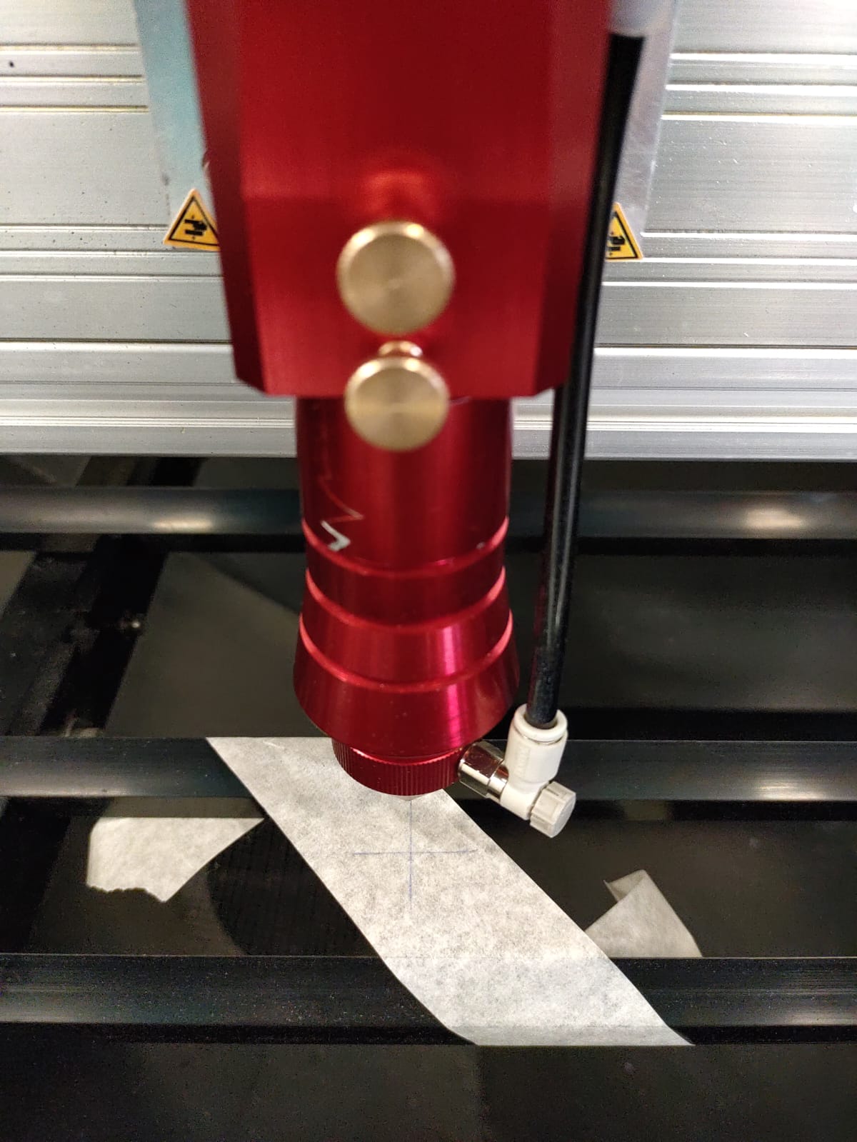
### Test laser source alignment
[Section titled “Test laser source alignment”](#test-laser-source-alignment)
1. **Unscrew lower lens shaft part** and set aside
2. **Stick new masking tape** over the plus sign
3. **Set a pulse**
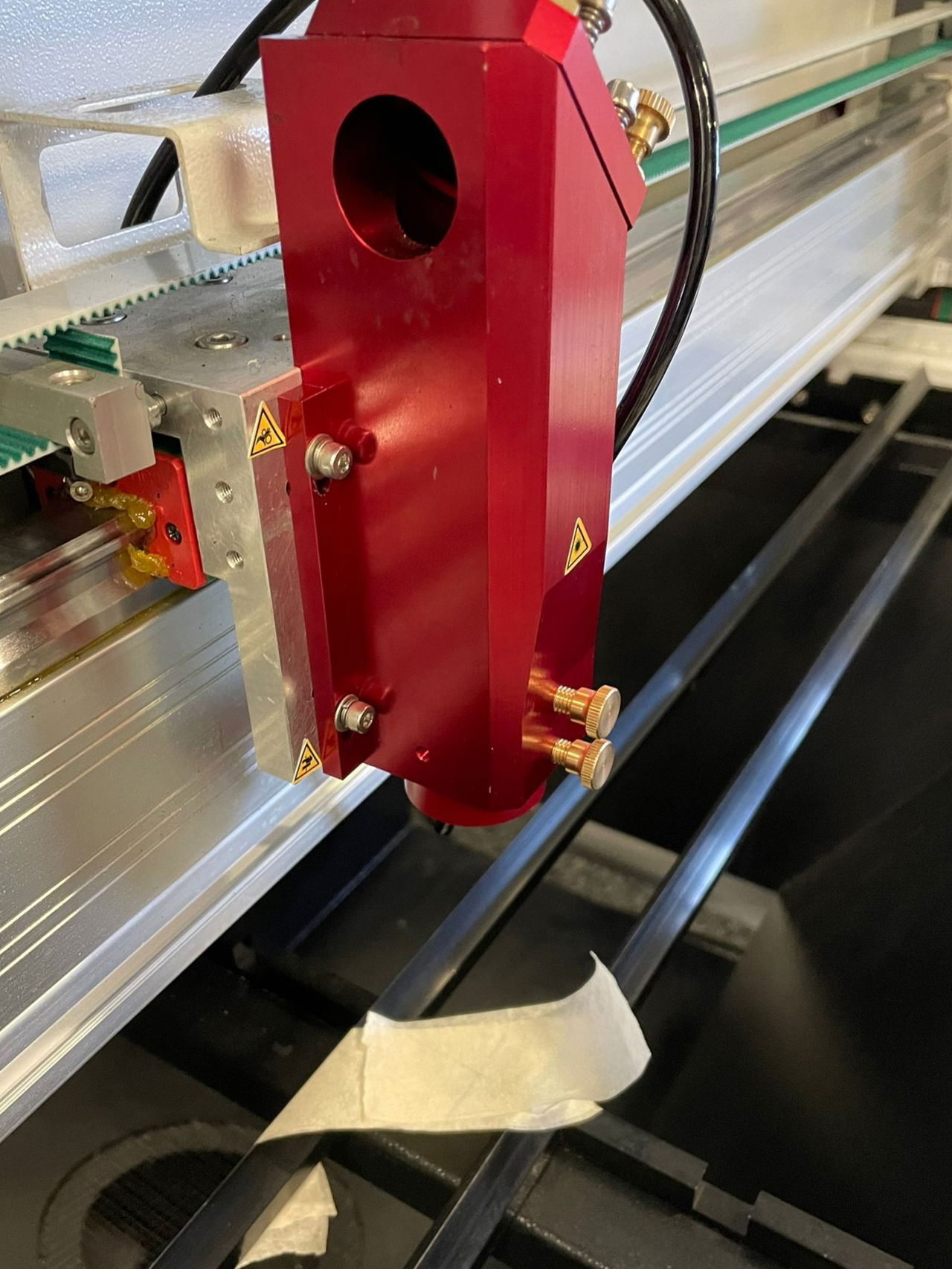
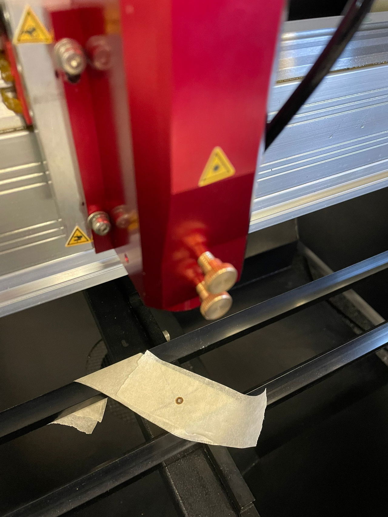
**Check result:** The pulse should be centered on the plus sign. If not, the laser source needs adjustment.
### Adjust laser source if needed
[Section titled “Adjust laser source if needed”](#adjust-laser-source-if-needed)
High voltage is lethal
Only qualified technicians may perform laser source adjustments. Turn off the machine and wait 24 hours before opening the laser source cover to allow capacitors to discharge.
**Access the laser source:**
1. Locate the laser source on the bridge
2. Remove the Allen bolts securing the panel
3. Carefully remove the cover
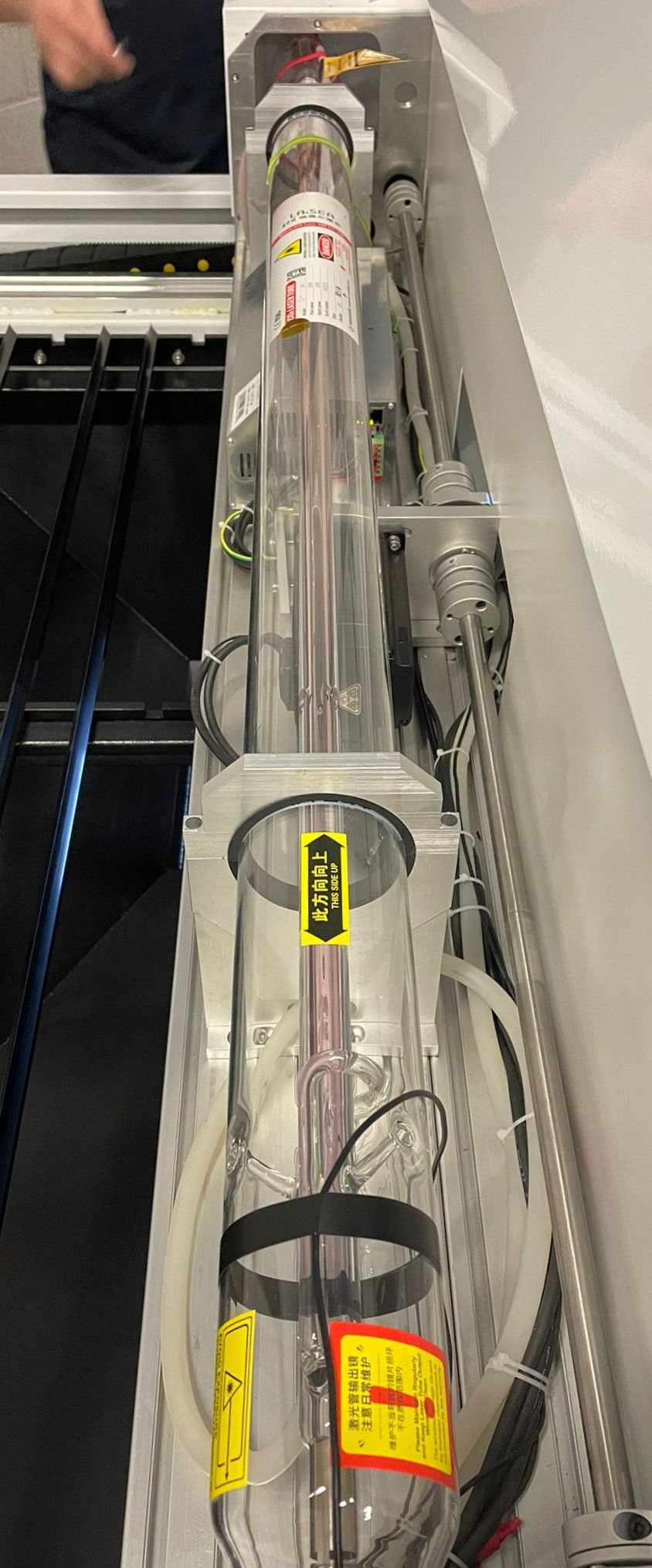
**Adjustment basics:**
The laser source sits in 2 holders that can be adjusted. Always adjust the holder furthest from the mirrors for more precise control.
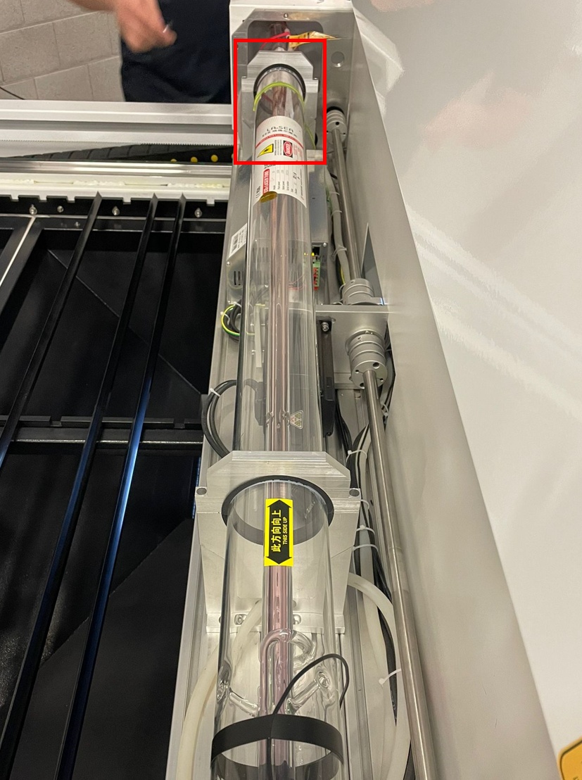
Support the holder
When adjusting height, support the holder to prevent it from suddenly dropping. If it drops, you’ll lose your reference point and have to start over.
**Adjustment effects:**
* **Adjusting source height (up/down):** Beam moves left or right on work area
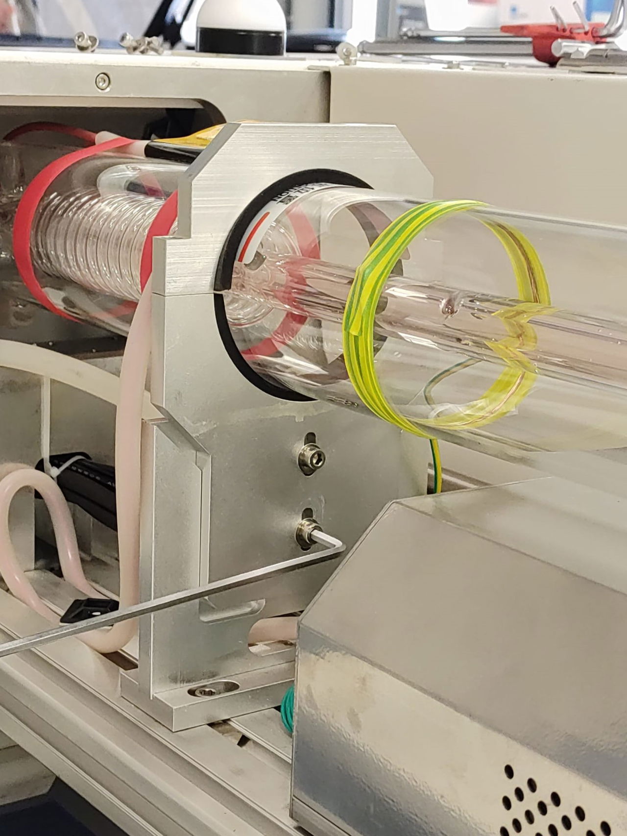
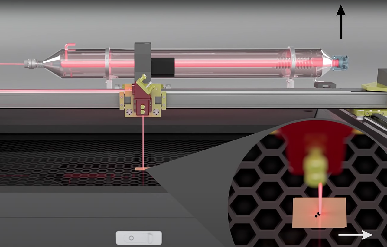
* **Adjusting source position (left/right):** Beam moves forward or backward on work area
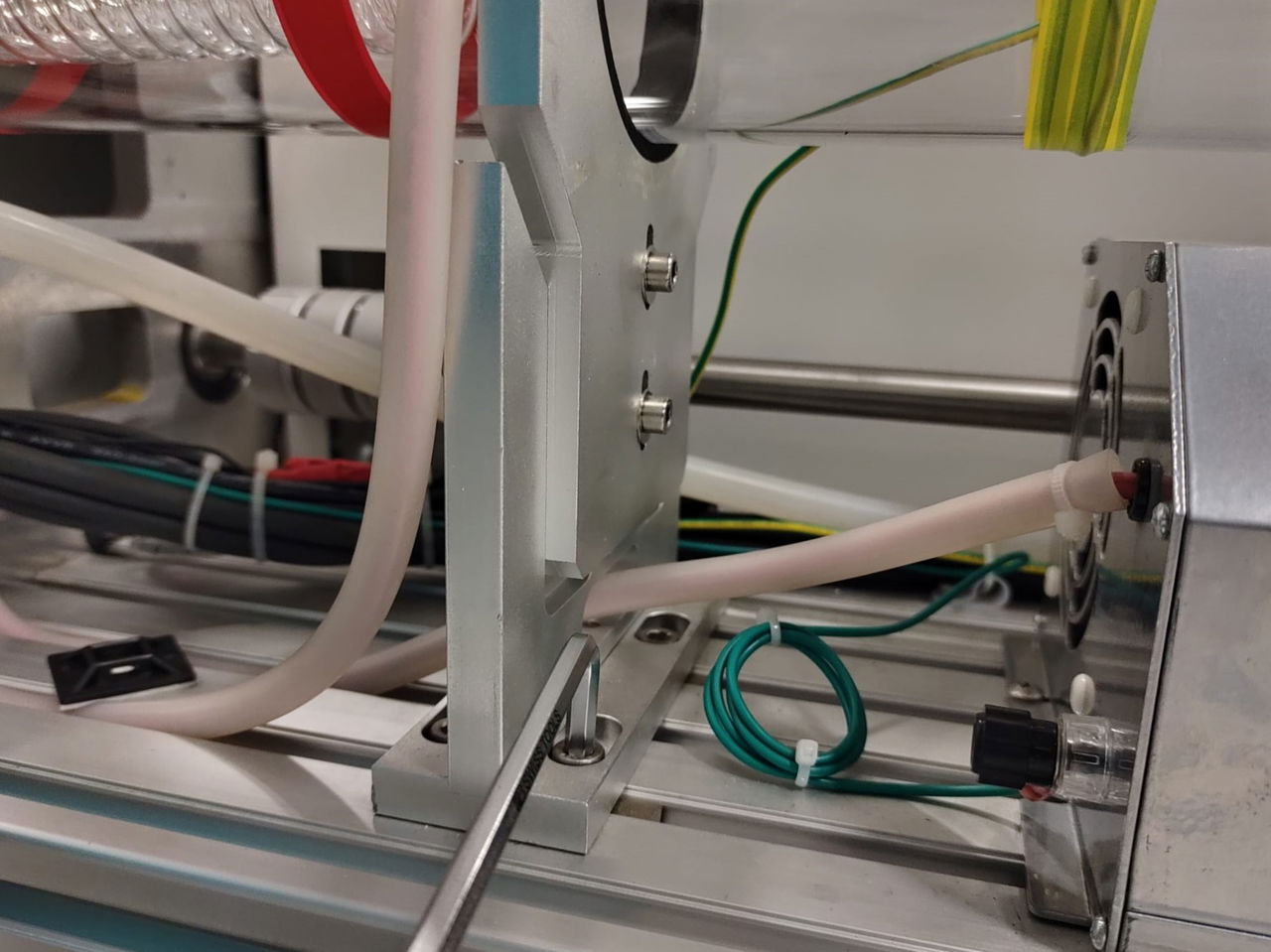
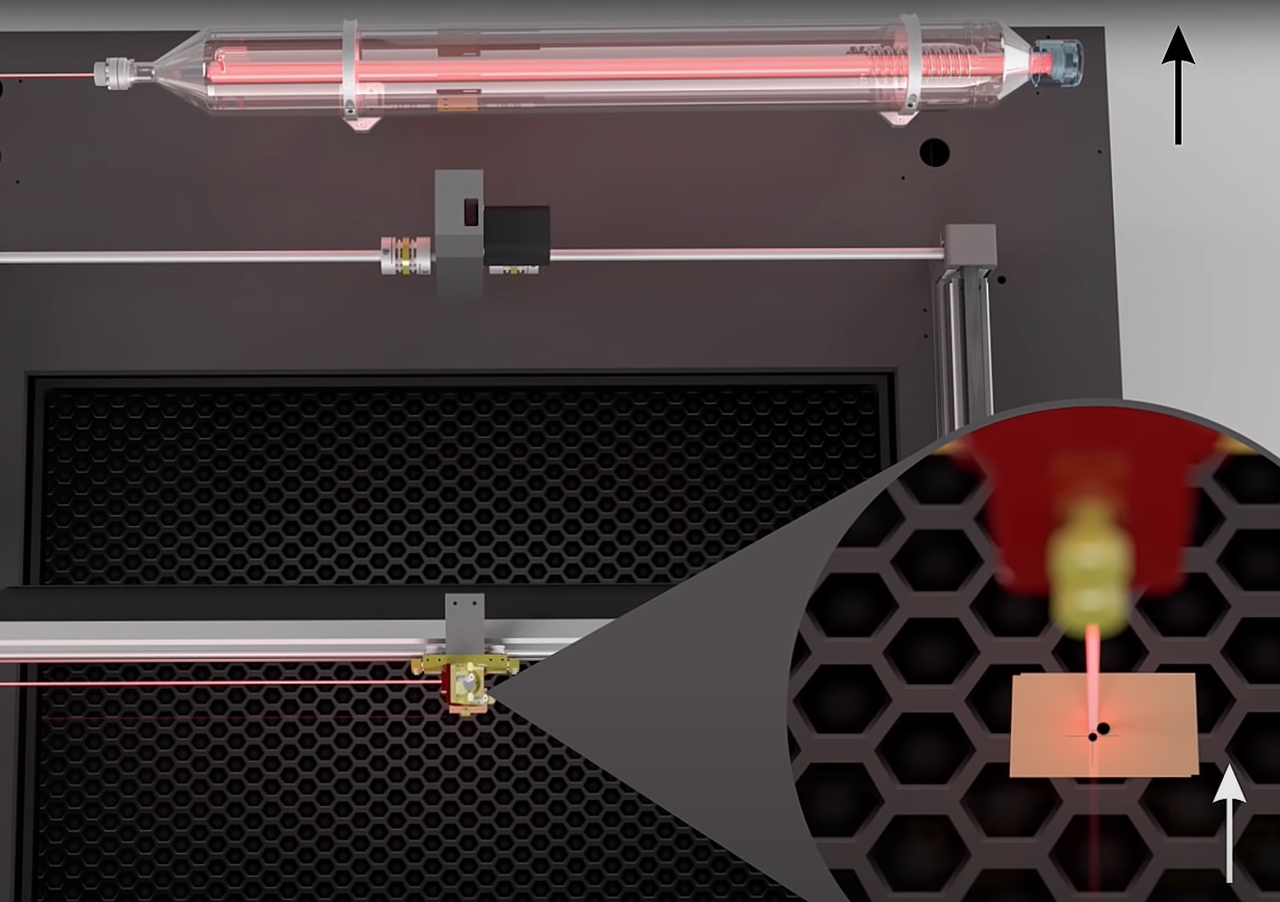
**Adjustment procedure:**
1. Make small adjustments to the laser source holder
2. Repeat the plus test at the laser head
3. Continue until pulse is centered on the plus sign
4. Verify entire mirror alignment once more to ensure everything is still properly aligned
## After alignment
[Section titled “After alignment”](#after-alignment)
Once alignment is complete:
1. **Reassemble all components** (lens shaft, covers, panels)
2. **Run a test job** to verify cutting performance across the work area
3. **Document the date** for your maintenance records
Regular alignment checks
Check alignment every 3 to 6 months or whenever you notice power loss or inconsistent results across the work area.
## Need help?
[Section titled “Need help?”](#need-help)
If you experience difficulties with alignment or results are still poor after alignment, [submit a ticket](/en/contact) for technical support.
## Related articles
[Section titled “Related articles”](#related-articles)
* [Cleaning mirrors](/en/maintenance/optical-path/cleaning-mirrors)
* [Lens cleaning](/en/maintenance/optical-path/lens-cleaning)
* [Mirror alignment for standard machines](/en/maintenance/optical-path/mirror-alignment)
# Materials and parameters
### Lasersprays
***
[CerMark LMM-6000CerMark LMM-6000 is a laser spray that can be used to mark certain metals with a CO₂ laser.](/en/materials-and-parameters/lasersprays/cermark-lmm6000)
[>](/en/materials-and-parameters/lasersprays/cermark-lmm6000)
[CerMark LMC-6044PCerMark LMC-6044P is a laser spray that can be used to mark glass and ceramics, for example, with a CO₂ laser.](/en/materials-and-parameters/lasersprays/cermark-lmm6044p)
[>](/en/materials-and-parameters/lasersprays/cermark-lmm6044p)
[CerMark UltraCerMark Ultra is a laser spray that can be used to mark certain metals, glass and ceramics with a CO₂ laser.](/en/materials-and-parameters/lasersprays/cermark-ultra)
[>](/en/materials-and-parameters/lasersprays/cermark-ultra)
[TherMark LMM-14TherMark LMM-14 is a laser spray that can be used to mark certain metals with a CO₂ laser.](/en/materials-and-parameters/lasersprays/thermark-lmm14)
[>](/en/materials-and-parameters/lasersprays/thermark-lmm14)
[Why use a lasersprayYou can read why you can use a laser spray here](/en/materials-and-parameters/lasersprays/why-use-a-laserspray)
[>](/en/materials-and-parameters/lasersprays/why-use-a-laserspray)
### Materials
***
[How can I find the right parameters for my material?Here you can find more information about how to find the right parameters for your material.](/en/materials-and-parameters/materials/how-to-adjust-for-a-material)
[>](/en/materials-and-parameters/materials/how-to-adjust-for-a-material)
### Parameters
***
[Indication parameters cutting, 100 W CO₂Parameters to try when cutting with a 100 W CO₂ laser source](/en/materials-and-parameters/parameters/example-parameters-100w-co2-cutting)
[>](/en/materials-and-parameters/parameters/example-parameters-100w-co2-cutting)
[Indication parameters engraving, 100 W CO₂Parameters to try when engraving with a 100 W CO₂ laser source](/en/materials-and-parameters/parameters/example-parameters-100w-co2-engraving)
[>](/en/materials-and-parameters/parameters/example-parameters-100w-co2-engraving)
[Importing the BRM Material Library in LightBurnStep-by-step guide for downloading and importing the free BRM material library into LightBurn, with parameter sets for 100 W, 150 W, and 300 W CO₂ laser sources.](/en/materials-and-parameters/parameters/importing-brm-material-library)
[>](/en/materials-and-parameters/parameters/importing-brm-material-library)
# CerMark LMM-6000
> CerMark LMM-6000 is a laser spray that can be used to mark certain metals with a CO₂ laser.
CerMark LMM-6000 is a laser spray that can be used to mark certain metals with a CO₂ laser.
Laser marking with CerMark LMM-6000 is possible on a large number of metals. CerMark LMM-6000 gives great results on stainless steel, titanium and steel. It is however necessary to make some samples to determine which machine parameters are needed. The underlying material, laser type, power and speed all affect the final result. It is also important to apply an even layer of CerMark LMM-6000.
## How do I use CerMark LMM-6000?
[Section titled “How do I use CerMark LMM-6000?”](#how-do-i-use-cermark-lmm-6000)
CerMark LMM-6000 is ready for use. Shake the spray can vigorously for a few minutes. Make sure that you can hear the ball rattling in the can. Then continue shaking for at least 2 more minutes. If the spray can is not shaken well, the coating and the solvent cannot mix well. This will cause the nozzle to clog. When this happens, the CerMark LMM-6000 cannot be applied evenly to the material.
Make sure that the material you want to engrave is free of grease and dust. You can degrease the material with alcohol. After degreasing the material, apply a thin, even layer of coating in one or two coats to get the best result. Make sure the coating is completely dry before you start marking! It takes a few minutes to dry if you have applied a thin, even layer. You can also place the wet object in an oven or use a hair dryer to dry the coating if you are pressed for time.
If the coating is applied too thickly, it takes more time to dry and much more power from the machine to achieve a good result. You can also coat less surface area. Unfortunately, we cannot give an estimate of the total surface area that can be coated. This depends on the thickness of the layer of coating you apply and whether you apply 1 or 2 coats.
We recommend applying the CerMark LMM-6000 in a well-ventilated area.
After marking, the coating can be rinsed off with lukewarm water. CerMark LMM-6000 provides a semi-permanent, black-colored marking on the material.

## How do I store the CerMark LMM-6000?
[Section titled “How do I store the CerMark LMM-6000?”](#how-do-i-store-the-cermark-lmm-6000)
When you have finished using the CerMark LMM-6000, make sure that you turn the spray can upside down and spray until no more comes out. This keeps the nozzle open. When storing the spray can, lay it on its side.
After opening, the CerMark has a limited shelf life, keep this in mind. You can already apply the CerMark LMM-6000 to our material and then store this material until you want to mark it. Be careful when putting it away so that it does not get scratched or anything like that.
If you have any questions, feel free to create a [ticket](/en/contact).
Download the MSDS [here](/en/downloads/msds/cermark).
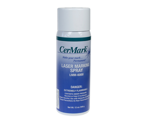
# CerMark LMC-6044P
> CerMark LMC-6044P is a laser spray that can be used to mark glass and ceramics, for example, with a CO₂ laser.
CerMark LMC-6044P is a laser spray that can be used to mark glass and ceramics, for example, with a CO₂ laser.
Laser marking with CerMark LMC-6044P is possible on a variety of materials. It gives a beautiful result on glass, ceramics, porcelain, glass bottles and tableware, for example. It is however necessary to make some samples to determine which machine parameters are needed. The underlying material, laser type, power and speed all affect the final result. It is also important to apply an even layer of CerMark LMC-6044P.
## How do I use CerMark LMC-6044P?
[Section titled “How do I use CerMark LMC-6044P?”](#how-do-i-use-cermark-lmc-6044p)
CerMark LMC-6044P is ready for use. Shake the spray can vigorously for a few minutes. Make sure that you can hear the ball rattling in the can. Then continue shaking for at least 2 more minutes. If the spray can is not shaken well, the coating and the solvent cannot mix well. This will cause the nozzle to clog. When this happens, the CerMark LMC-6044P cannot be applied evenly to the material.
Make sure that the material you want to engrave is free of grease and dust. You can degrease the material with alcohol. After degreasing the material, apply a thin, even layer of coating in one or two coats to get the best result. We recommend applying the CerMark LMC-6044P in a well-ventilated room. Make sure the coating is completely dry before you start marking! It takes a few minutes to dry if you have applied a thin, even layer. You can also place the wet object in an oven or use a hair dryer to dry the coating if you are pressed for time.
If the coating is applied too thickly, it takes more time to dry and much more power from the machine to achieve a good result.
CerMark LMC-6044P dries as a powder that is easy to remove after marking. You can rinse the coating off with lukewarm water. It is recommended not to mark the material too long after applying the CerMark. Be careful not to touch the coating as it damages quite quickly. Unfortunately, we cannot give an estimate of the total surface area that can be coated. This depends on the thickness of the coating and whether you apply 1 or 2 layers. It is important to use less power and speed. High power can damage glass substrates and this should be avoided. You will have to test with this. Give it a try with some test versions in order to come up with the best settings for your item.
## How do I store the CerMark LMC-6044P?
[Section titled “How do I store the CerMark LMC-6044P?”](#how-do-i-store-the-cermark-lmc-6044p)
When you are finished using the CerMark LMC-6044P, make sure you turn the spray can upside down and spray. This will keep the nozzle open. Store the spray can by laying it down on its side. After opening, the CerMark has a limited shelf life, keep this in mind.
If you have any questions, feel free to create a [ticket](/en/contact).
Download the MSDS [here.](/en/downloads/msds/cermark)
# CerMark Ultra
> CerMark Ultra is a laser spray that can be used to mark certain metals, glass and ceramics with a CO₂ laser.
CerMark Ultra is a laser spray that can be used to mark certain metals, glass and ceramics with a CO₂ laser.
Laser marking with CerMark Ultra is possible on a large number of materials. CerMark Ultra gives great results on stainless steel, aluminum, titanium, slate, glass, tiles and ceramics. It is however necessary to make some samples to determine which machine parameters are needed. The underlying material, laser type, power and speed all affect the final result. It is also important to apply an even layer of CerMark Ultra.
## How do I use CerMark Ultra?
[Section titled “How do I use CerMark Ultra?”](#how-do-i-use-cermark-ultra)
CerMark Ultra is ready for use. Shake the spray can vigorously for a few minutes. Make sure that you can hear the ball rattling in the can. Then continue shaking for 2 more minutes. If the spray can is not shaken well, the coating and the solvent cannot mix well. This will cause the nozzle to clog. When this happens, the CerMark Ultra cannot be applied evenly to the material.
Make sure that the material you want to engrave is free of grease and dust. You can degrease the material with alcohol. After degreasing the material, apply a thin, even layer of coating in one or two coats to get the best result. Make sure the coating is completely dry before you start marking! It takes a few minutes to dry if you have applied a thin, even layer.
We recommend applying the CerMark Ultra in a well-ventilated area.
If the coating is applied too thickly, it takes more time to dry and much more power from the machine to achieve a good result. You can also coat less surface area. Unfortunately, we cannot give an estimate of the total surface area that can be coated. This depends on the thickness of the layer of coating you apply and whether you apply 1 or 2 coats.
After marking, the coating can be rinsed off with lukewarm water. CerMark Ultra provides a semi-permanent, black-colored marking on the material.
## How do I store the CerMark Ultra?
[Section titled “How do I store the CerMark Ultra?”](#how-do-i-store-the-cermark-ultra)
When you have finished using the CerMark Ultra, make sure that you turn the spray can upside down and spray until no more comes out. This keeps the nozzle open. If you store the spray can lay it on its side.
After opening, the CerMark has a limited shelf life, keep this in mind. You can already apply the CerMark Ultra to your material and then store this material until you want to mark it. Be careful when putting it away so that it does not get scratched or anything like that.
If you have any questions, feel free to create a [ticket](/en/contact).
Download the MSDS [here](/en/downloads/msds/cermark).
# TherMark LMM-14
> TherMark LMM-14 is a laser spray that can be used to mark certain metals with a CO₂ laser.
TherMark LMM-14 is a laser spray that can be used to mark certain metals with a CO₂ laser.
Laser marking with TherMark LMM-14 is possible on a large number of metals. TherMark LMM-14 gives great results on chrome-plated stainless steel, aluminum, silver-plated brass and gold-plated galvanized steel. It is however necessary to make some samples to determine which machine parameters are needed. The underlying material, laser type, power and speed all affect the final result. It is also important to apply an even layer of TherMark LMM-14.
## How do I use TherMark LMM-14?
[Section titled “How do I use TherMark LMM-14?”](#how-do-i-use-thermark-lmm-14)
TherMark LMM-14 is ready for use. Shake the spray can vigorously for a few minutes. Make sure that you can hear the ball rattling in the can. Then continue shaking for 2 minutes. If the spray can is not shaken well, the coating and the solvent cannot mix well. This will cause the nozzle to clog. When this happens, the TherMark LMM-14 cannot be applied evenly to the material.
Make sure that the material you want to engrave is free of grease and dust. You can degrease the material with alcohol. After you have degreased the material, apply a thin, even coat, in one or two passes, to get the best results. If the coating is applied too thick, it takes more time to dry and much more power from the machine to achieve a good result. Make sure the coating is completely dry before you start marking! It takes a few minutes to dry if you have applied a thin, even layer. You can also place the wet object in an oven or use a hair dryer to dry the coating if you are pressed for time.
We recommend applying the TherMark LMM-14 in a well-ventilated area.
TherMark LMM-14 dries as a powder that is easy to remove after marking. It is recommended not to mark the material too long after applying the TherMark. Be careful not to touch the coating as it damages quite quickly. Unfortunately, we cannot give an estimate of the total surface area that can be coated. This depends on the thickness of the coating and whether you apply 1 or 2 layers.
After marking, the coating can be rinsed off the material with lukewarm water. TherMark LMM-14 provides a semi-permanent, black-colored marking on the material.

## How do I store the TherMark LMM-14?
[Section titled “How do I store the TherMark LMM-14?”](#how-do-i-store-the-thermark-lmm-14)
When you are finished using the TherMark LMM-14, make sure you turn the spray can upside down and spray. This will keep the nozzle open. Store the spray can by laying it down on its side. After opening, the TherMark has a limited shelf life, keep this in mind.
If you have any questions, feel free to create a [ticket](/en/contact).
Download the MSDS [here](/en/downloads/msds/cermark).
# Why use a laserspray
> You can read why you can use a laser spray here
A laser spray is a spray that you can spray on your material before marking/engraving. The spray turns your engraving black / dark gray and can provide a nice contrast to your material. You do not use spray if you are going to engrave, for example, wood or plastic (acrylic, PE, etc). You use the spray for metals and, for example, glass and ceramics.
## Metal
[Section titled “Metal”](#metal)
The use of a laser spray is necessary when engraving / marking metals. Without using a laser spray, you cannot mark / engrave metals. If you do, the laser beam reflects back to the laser source, causing it to malfunction. Engraving / marking a metal without the use of a laser spray also voids the warranty on the laser source, if it is actually still under warranty.

## Non-metals
[Section titled “Non-metals”](#non-metals)
When engraving glass, ceramics and porcelain, for example, laser spray can be a nice addition. It is not necessary to use it with these materials. If you engrave these materials without using a laser spray, the engraving will blend out a bit. For example, if you engrave glass, the engraving will be somewhat whitish and fairly dull. From a distance, the engraving is actually not that visible. If you use a laser spray, the engraving becomes black / dark gray and is immediately noticeable because there is a nice contrast between glass and engraving.
## Various sprays
[Section titled “Various sprays”](#various-sprays)
There are various laser sprays. We have 4 in our assortment that all leave a black / dark gray semi-permanent engraving. The difference in the sprays is the material they can be used on.
For more information about laser spray for hard metals look [here](/en/materials-and-parameters/lasersprays/cermark-lmm6000), for more information about laser spray for soft metals look [here](/en/materials-and-parameters/lasersprays/thermark-lmm14).
Should you want to know more about laser spray for glass and ceramics, among others, you can look [here](/en/materials-and-parameters/lasersprays/cermark-lmm6044p).
There is also a laser spray that can be used on metals as well as glass and ceramics, see [here](/en/materials-and-parameters/lasersprays/cermark-ultra) for more information for that laser spray.
# How can I find the right parameters for my material?
> Here you can find more information about how to find the right parameters for your material.
You have a material you did not process before with the BRM laser machine. How do you find the correct parameters to get a good result?
## Is my material suitable for the BRM laser?
[Section titled “Is my material suitable for the BRM laser?”](#is-my-material-suitable-for-the-brm-laser)
Before you can start processing material with the BRM laser machine, you need to check whether the material is suitable for processing with a laser beam. Not all materials are qualified for processing. There are materials that can cause damage to the machine and to persons working with the machine who are in the same room. When you process a material such as PVC with a laser, harmful gases are released that cause the machine to rust. Moreover, the generated gases are carcinogenic. That is why you do not want to use the laser machine to process such materials.
Materials that contain a negatively charged particle (anion) must never be processed with the machine. Here are some examples. Materials containing the elements listed below, cannot be processed with the BRM laser:
* Fluoride **F-**
* Chloride **Cl-**
* Bromide **Br-**
* Iodide **I-**
If you are unsure whether your material contains one of these elements or another anion, you can request the MSDS (**M**aterial **S**afety **D**ata **S**heet) from your material supplier. It states what a material is made of.
If you are not sure how to read an MSDS, please check this article: [How to read an MSDS?](/en/tips-and-tricks/machines/what-is-a-msds)
NOTE!!! Anions and Chloride are very hazardous to one’s health.
BRM Lasers strongly recommends not to work with PVC or other materials containing Anions / Chloride with a laser machine. Processing these materials will terminate the warranty on your machine.
## Reflective materials
[Section titled “Reflective materials”](#reflective-materials)
Reflective materials are also not suitable for cutting. Think of metals, for example. Not all of these materials are reflective for humans, but they are for the machine. These materials are reflective at the wavelength of the laser beam. You also cannot cut glass with the BRM laser machine.
However, some of these materials, like glass, are suitable for marking with the addition of a laser spray. This also applies to anodized aluminum.
## What is the difference between marking and engraving?
[Section titled “What is the difference between marking and engraving?”](#what-is-the-difference-between-marking-and-engraving)
When engraving a material, you remove material with the laser beam. That is what you do with, for example, wood and acrylic.
Marking can be done by heating the material and also by applying something to it, such as a laser spray. That is what you do with stainless steel, for instance. You spray a layer of laser spray on stainless steel, after which you can mark over it with the laser.
Both options - marking and engraving - are named **\[Scan]** or **\[Fill]** in the software.


## My material is suitable for processing with the laser machine, how do I find the right parameters?
[Section titled “My material is suitable for processing with the laser machine, how do I find the right parameters?”](#my-material-is-suitable-for-processing-with-the-laser-machine-how-do-i-find-the-right-parameters)
To find the correct parameters for your material, we have to make a distinction between cutting and engraving / marking. We also have to make a difference between materials such as plastic and wood.
## How do I find good parameters for cutting a plastic?
[Section titled “How do I find good parameters for cutting a plastic?”](#how-do-i-find-good-parameters-for-cutting-a-plastic)
It is wise to use a small shape. You can then test several settings, and you will not lose a lot of material. A square of 5 × 5 cm is a good example. Choose a low speed with high power. A speed of 5 mm/s and 85 % power are good starting points. You will see that you can cut through your material but that the result can be improved.
If you notice a lot of melting, a deposit and/or leak marks, the material is heating up too much. Are the edges reasonably clean, without white deposit and leakage traces? Then you are already in the right direction in terms of speed.
If you don’t have a clean edge yet, you can take your speed up a notch. You want to keep the power on the high side. So when you have a melt, a deposit or leak marks, you will initially increase the speed a little. Note that it is important to never input less than 15 % power. The laser source has a switching point and this is around 15 %. If you enter 14 or less, the source may not turn on or the source may still turn on and off, preventing you from cutting.
Not until the speed is so high that the corners do not turn out well, do you adjust the power. You then go back to the speed at which the corners are crisp. After that, you reduce the power in small steps.
When a white deposit appears on the cutting edge you can also reduce the air supply. Make sure you keep using air, and never turn off the air supply. Please also make sure that no flame is caused. Should that happen, you will have to add a little more air.
You can also set the min and max power. The min power is the power used for the corners and curves. If you see that the edges are turning out nicely but the corners are getting very dark, you can lower the min power. Lower the min power until the corners are also turning out fine. If you set the min power too low your product may be stuck somewhere in the corners. If this is the case, increase the min power slightly. There can be quite a difference between the min and the max power.

## How do I find good parameters for engraving a plastic?
[Section titled “How do I find good parameters for engraving a plastic?”](#how-do-i-find-good-parameters-for-engraving-a-plastic)
Firstly, it is smart to use small shapes to avoid losing too much material. Consider a square of 5 × 5 cm, for example. If you want to engrave a picture, you can select a part of it to test. Do not scale the picture as this will give a different result.
When engraving / marking, 3 elements are important.
* Speed
* Power
* Interval
Note that intervals are not used when cutting material, they are only used for engraving / marking. The interval is the horizontal distance between the engraving lines. You can adjust it to bring the lines closer or further apart. Engraving is faster when the interval is higher. There will be more distance between the engraving lines and as a result, fewer lines will be engraved. However, you do lose some detail. We recommend keeping the interval between 0.06 and 0.12.


To get the desired parameters, you can start with a speed of 400 mm/s. Engraving at a higher speed can result in the loss of small details. Choose a low power level, for example, 20 %. From here, you can either reduce or increase the power. Make sure that you do not reduce the power below about 15 %, as there is a risk that the laser will not be activated. If the situation requires less power, try it and otherwise increase the speed slightly.
When it comes to engraving / marking, it is somewhat more difficult to define when an engraving / marking is of quality. When it comes to engraving, much depends on taste. You might like a light engraving. However, you may also prefer a deeper engraving.
Detail is often more important when engraving a picture than when engraving a serial number, for example. That is why you might want to use a different interval when you engrave a picture than when you choose to engrave a serial number in the same material.
Use less power if your engraving is too deep. If the engraving is not deep enough, use more power. Note that it is important to never input less than 15 % power. The laser source has a switching point and this is around 15 %. If you enter 14 or less, the source may not turn on or the source may still turn on and off, preventing you from engraving.
If you are losing detail, you can either adjust the interval or start engraving slower. If you see overlap in the engraving, you can increase the interval to eliminate that. In any case, do not use too much air but be sure to always have at least some air.
## How do I find good parameters for cutting wood?
[Section titled “How do I find good parameters for cutting wood?”](#how-do-i-find-good-parameters-for-cutting-wood)
Firstly, it is smart to use small shapes to avoid losing too much material. You can then test several settings, and you will not lose a lot of material. Consider a square of 5 × 5 cm, for example. Choose a low speed with high power. A speed of 5 mm/s and 85 % power are good starting points. You will see that you can cut through your material but that the result can be improved.
If you cut too slowly, a flame will appear. When this happens, you will have to cut faster.
Not until you get to a speed where the corners don’t turn out well, do you adjust the power. You then go back to the speed at which the corners are crisp. After that, you reduce the power in small steps. Note that it is important to never input less than 15 % power. The laser source has a switching point and this is around 15 %. If you enter 14 or less, the source may not turn on or the source may still turn on and off, preventing you from cutting.
If you have cut your wood and the entire edge of your product is charred, the first thing you do is increase the speed. Only until your corners don’t turn out well, do you decrease your power. Then the edges will become cleaner and less dark.
If a rim of dust appears on the top of your material, you should turn down the air supply. Basically, with wood, you can open up the air supply completely. Not until you get a rim of dust do you reduce the air slightly.
You can also set the min and max power. The min power is the power used for the corners and curves. If you see that the edges are turning out nicely but the corners are getting very dark, you can lower the min power. Lower the min power until the corners are also turning out fine. If you set the min power too low your product may be stuck somewhere in the corners. If this is the case, increase the min power slightly. There can be quite a difference between the min and the max power.

## How do I find good parameters for engraving wood?
[Section titled “How do I find good parameters for engraving wood?”](#how-do-i-find-good-parameters-for-engraving-wood)
Firstly, it is smart to use small shapes to avoid losing too much material. Consider a square of 5 × 5 cm, for example. If you want to engrave a picture, you can select a part of it to test. Do not scale the picture as this will give a different result.
When engraving / marking, 3 elements are important.
* Speed
* Power
* Interval
Note that intervals are not used when cutting material, they are only used for engraving / marking. The interval is the horizontal distance between the engraving lines. You can adjust it to bring the lines closer or further apart. Engraving is faster when the interval is higher. There will be more distance between the engraving lines and as a result, fewer lines will be engraved. However, you do lose some detail. We recommend keeping the interval between 0.06 and 0.12. To get the desired parameters, you can start with a speed of 400 mm/s. Engraving at a higher speed can result in the loss of small details. Choose a low power level, for example, 20 %. Note that it is important to never input less than 15 % power. The laser source has a switching point and this is around 15 %. If you enter 14 or less, the source may not turn on or the source may still turn on and off, preventing you from engraving.
Deposits are a common phenomenon with wood. The smoke released during engraving quickly gets into the pores of the engraving. Use less air to reduce the deposits. Always keep using some air. Otherwise, the smoke will clog up the lens and break it. Check the lens regularly if you decide to add little air. Alternatively, you can apply a thin layer of masking tape to your wood and then engrave it. That will reduce the deposit. However, you will have to adjust your parameters slightly because you are engraving through an extra layer. Afterwards remove the tape and you will see that you have better contrast than when you engrave without the layer of tape.
## Engraving a mirror
[Section titled “Engraving a mirror”](#engraving-a-mirror)
With the BRM laser machine, you can also engrave a mirror. On the back of a mirror there is a thin layer, you can engrave this layer away. Never press the Pulse button when engraving a mirror! This will break the mirror!
Make sure to mirror your drawing, as you are engraving on the back of the mirror.
Start here with a speed of 400 mm/s. If you engrave faster you can lose some details. Because the layer on the mirror is thin you use little power. Start for example with a power of 20 %. You can always add a little more power. However, you can also engrave slower with little power. Note that it is important to never input less than 15 % power. The laser source has a switching point and this is around 15 %. If you enter 14 or less, the source may not turn on or the source may still turn on and off, preventing you from engraving.
## Engraving / marking glass
[Section titled “Engraving / marking glass”](#engraving--marking-glass)
It’s also possible to engrave / mark glass. You can use a laser spray to add contrast.
Please note that when engraving / marking glass, it is important never to press the Pulse button. Pressing the Pulse button will break the glass. The glass wants to expand due to the sudden heat, but this is impossible. It will cause the glass to break.
When engraving / marking glass, start with a speed of, for example, 400 mm/s at 20 % power. If required, you can add some more power. Note that it is important to never input less than 15 % power. The laser source has a switching point and this is around 15 %. If you enter 14 or less, the source may not turn on or the source may still turn on and off, preventing you from engraving.
For a good result, you can cover your glass object with a wet newspaper. Wet paper cools the glass. It ensures that the deposit will not get on your engraving. One layer of paper is enough. However, you will need to use a little more power because you will also need to engrave / mark through the layer of paper. If you engrave / mark a large area, you can spray the paper layer with water every now and then.
## Marking metal
[Section titled “Marking metal”](#marking-metal)
With the BRM laser machine, you can also mark metal. However, you’ll need to use a laser spray to do so. The laser spray ensures that the material no longer reflects. The laser spray also has a color, black, which gives your marking that same color and provides a contrast to the underlying material.
**Without adding laser spray you cannot mark metals! The laser beam reflects back to the laser source and causes it to break! If you do mark metals without a laser spray and the laser source is damaged, this is not covered by warranty!**
Start with a speed of 400 mm/s and a power of 20 %. From here you can increase your power slightly to achieve a pleasing result. Note that it is important to never input less than 15 % power. The laser source has a switching point and this is around 15 %. If you enter 14 or less, the source may not turn on or the source may still turn on and off, preventing you from engraving.
After marking, you can wash the spray off your material with lukewarm water and what remains is the grey-black marking. For more information regarding laser sprays, please click [here.](/en/materials-and-parameters/lasersprays/why-use-a-laserspray)
# Indication parameters cutting, 100 W CO₂
> Parameters to try when cutting with a 100 W CO₂ laser source
In the list below, you will find different materials and the corresponding indication parameters for cutting.
Note that these values are indications only!
Each laser source and power supply are unique. Because of this, each machine is different. Use these values as a guide.
If you use these values but the result is not optimal, try other values. You can, for example, cut 5 x 5 cm squares with different cutting values and choose which value fits best. Note that it is important to never input less than 15 % power. The laser source has a switching point and this is around 15 %. If you enter 14 or less, the source may not turn on or the source may still turn on and off, preventing you from cutting.
You can find more information on how to find the parameters [here](/en/materials-and-parameters/materials/how-to-adjust-for-a-material).
| Materials | Thickness | Power | Speed | Lens | Air pressure | Remarks |
| ------------------ | --------- | ----- | --------- | -------- | ------------ | -------------------------- |
| Acrylic | 2 mm | 85 % | 45 mm/s | 63.5 mm | Low | |
| Acrylic | 3 mm | 85 % | 27 mm/s | 63.5 mm | Low | |
| Acrylic | 4 mm | 85 % | 24 mm/s | 63.5 mm | Low | |
| Acrylic | 5 mm | 85 % | 16 mm/s | 63.5 mm | Low | |
| Acrylic | 6 mm | 85 % | 13 mm/s | 63.5 mm | Low | |
| Acrylic | 8 mm | 85 % | 8 mm/s | 101.6 mm | Low | |
| Acrylic | 10 mm | 85 % | 5 mm/s | 101.6 mm | Low | |
| Acrylic | 11 mm | 85 % | 4 mm/s | 101.6 mm | Low | |
| Acrylic | 15 mm | 98 % | 3 mm/s | 101.6 mm | Low | |
| Acrylic | 19 mm | 98 % | 2 mm/s | 101.6 mm | Low | |
| Acrylic | 20 mm | 98 % | 1 mm/s | 101.6 mm | Low | |
| Carbon Fiber | 2 mm | 85 % | 8 mm/s | 63.5 mm | High | Compressor option required |
| Cardboard | 2 mm | 85 % | 220 mm/s | 63.5 mm | High | |
| Cardboard | 4 mm | 85 % | 80 mm/s | 63.5 mm | High | |
| Cardboard | 6 mm | 85 % | 57 mm/s | 63.5 mm | High | |
| Cotton Fabric | 0,5 mm | 85 % | 350 mm/s | 63.5 mm | Low | |
| Felt | 2 mm | 85 % | 130 mm/s | 63.5 mm | High | |
| Fish based leather | 2 mm | 50 % | 15 mm/s | 63.5 mm | High | |
| Foam Rubber | 40 mm | 85 % | 18 mm/s | 101.6 mm | High | |
| Foam Rubber | 70 mm | 85 % | 3 mm/s | 101.6 mm | High | Compressor option required |
| Hardboard (HDF) | 3 mm | 85 % | 25 mm/s | 63.5 mm | High | |
| Leather | 1 mm | 85 % | 120 mm/s | 63.5 mm | High | |
| Leather (Ridgid) | 3 mm | 85 % | 29 mm/s | 63.5 mm | High | |
| MDF | 8 mm | 85 % | 11 mm/s | 63.5 mm | High | |
| MDF | 10 mm | 85 % | 9 mm/s | 101.6 mm | High | |
| Multiplex Wood | 2 mm | 85 % | 47 mm/s | 101.6 mm | High | |
| Multiplex Wood | 3 mm | 85 % | 15 mm/s | 101.6 mm | High | |
| Paper 35-55 GSM | 1 mm | 15 % | 1000 mm/s | 63.5 mm | Low | |
| Paper 90-100 GSM | 1 mm | 20 % | 1000 mm/s | 63.5 mm | Low | |
| Paper 120-140 GSM | 1 mm | 30 % | 1000 mm/s | 63.5 mm | Low | |
| Paper 210-300 GSM | 1 mm | 40 % | 1000 mm/s | 63.5 mm | Low | |
| Particleboard | 8 mm | 85 % | 4 mm/s | 63.5 mm | High | |
| Plastic Foil | 0,1 mm | 35 % | 1000 mm/s | 63.5 mm | Low | |
| Plywood | 5 mm | 85 % | 45 mm/s | 63.5 mm | High | |
| Plywood | 10 mm | 85 % | 17 mm/s | 101.6 mm | High | |
| Polyethylene Foam | 20 mm | 85 % | 65 mm/s | 101.6 mm | High | |
| Polyethylene Foam | 25 mm | 85 % | 45 mm/s | 101.6 mm | High | Compressor option required |
| Soft Foam | 16 mm | 40 % | 80 mm/s | 101.6 mm | High | |
| Styrofoam | 2 mm | 85 % | 1000 mm/s | 63.5 mm | High | |
| Styrofoam | 4 mm | 85 % | 800 mm/s | 63.5 mm | High | |
| Styrofoam | 8 mm | 85 % | 600 mm/s | 63.5 mm | High | |
| Styrofoam | 10 mm | 85 % | 400 mm/s | 63.5 mm | High | |
| Styrofoam | 20 mm | 85 % | 200 mm/s | 101.6 mm | High | |
| Styrofoam | 30 mm | 85 % | 90 mm/s | 101.6 mm | High | |
| Styrofoam | 40 mm | 85 % | 40 mm/s | 101.6 mm | High | Compressor option required |
| Styrofoam | 50 mm | 85 % | 15 mm/s | 101.6 mm | High | Compressor option required |
# Indication parameters engraving, 100 W CO₂
> Parameters to try when engraving with a 100 W CO₂ laser source
In the list below, you will find different materials and the corresponding indication parameters for engraving.
Note that these values are indications only!
Each laser source and power supply are unique. Because of this, each machine is different. Use these values as a guide.
Engraving is ideally done with the 50.8 mm lens as it gives the thinnest line.
If you use these values but the result is not optimal, try other values. You can, for example, engrave 5 x 5 cm squares with different engraving values and choose which value fits best. Note that it is important to never input less than 15 % power. The laser source has a switching point and this is around 15 %. If you enter 14 or less, the source may not turn on or the source may still turn on and off, preventing you from engraving.
You can find more information on how to find the parameters [here](/en/materials-and-parameters/materials/how-to-adjust-for-a-material).
## Deep engravings
[Section titled “Deep engravings”](#deep-engravings)
The engravings will be deeper than 0.1 mm.
| Material | Power | Speed | Interval | Cermark |
| ----------------- | ----- | --------- | -------- | ------- |
| Acrylic | 85 % | 200 mm/s | 0.1 mm | |
| Cardboard | 85 % | 1000 mm/s | 0.12 mm | |
| Hardboard (HDF) | 85 % | 150 mm/s | 0.1 mm | |
| Leather | 85 % | 1000 mm/s | 0.1 mm | |
| Leather (Rigid) | 85 % | 500 mm/s | 0.1 mm | |
| MDF | 85 % | 500 mm/s | 0.1 mm | |
| Multiplex Wood | 85 % | 450 mm/s | 0.1 mm | |
| Particleboard | 85 % | 1000 mm/s | 0.1 mm | |
| Plywood | 85 % | 500 mm/s | 0.1 mm | |
| Polyethylene Foam | 35 % | 1000 mm/s | 0.12 mm | |
## Shallow engravings
[Section titled “Shallow engravings”](#shallow-engravings)
These engravings are more for the image quality, most of the time the engraving will be up to 0.1 mm deep.
| Material | Power | Speed | Interval | Cermark |
| --------------- | ----- | --------- | -------- | ------- |
| Acrylic | 25 % | 1000 mm/s | 0.1 mm | |
| Cardboard | 25 % | 1000 mm/s | 0.1 mm | |
| Hardboard (HDF) | 15 % | 1000 mm/s | 0.1 mm | |
| Leather | 15 % | 1000 mm/s | 0.1 mm | |
| Leather (Rigid) | 15 % | 1000 mm/s | 0.1 mm | |
| MDF | 40 % | 1000 mm/s | 0.1 mm | |
| Multiplex Wood | 15 % | 1000 mm/s | 0.1 mm | |
| Paper | 15 % | 1000 mm/s | 0.1 mm | |
| Particleboard | 40 % | 1000 mm/s | 0.1 mm | |
| Plywood | 25 % | 1000 mm/s | 0.1 mm | |
| Stainless Steel | 85 % | 500 mm/s | 0.06 mm | ✔ |
# Importing the BRM Material Library in LightBurn
> Step-by-step guide for downloading and importing the free BRM material library into LightBurn, with parameter sets for 100 W, 150 W, and 300 W CO₂ laser sources.
BRM maintains an extensive material library with tested cutting and engraving parameters for our CO₂ laser machines. The library is free to use and works directly inside LightBurn. This guide walks you through downloading, importing, and applying it to your projects.
## What you need
[Section titled “What you need”](#what-you-need)
* LightBurn installed on your computer
* A BRM laser machine, or knowledge of your laser source wattage (100 W, 150 W, 300 W)
* About 5 minutes
## Step 1: Download the library
[Section titled “Step 1: Download the library”](#step-1-download-the-library)
Download the library as a single .zip archive:
[Download the BRM Material Library](https://cdn.brmlasers.com/support/Software/brm-lasers-all-material-libraries.zip)
Extract the .zip file. You will get a folder called `Libraries` containing three subfolders, one per supported language:
* `EN` — English
* `DE` — German (Deutsch)
* `NL` — Dutch (Nederlands)
Inside each language folder, the files follow this naming pattern: BRM\_\[wattage]\_\[language].clb
For example, the English library for a 150 W laser source is: Libraries/EN/BRM\_150\_EN.clb
Pick the file that matches your laser source wattage and preferred language.
## Step 2: Open the Library panel in LightBurn
[Section titled “Step 2: Open the Library panel in LightBurn”](#step-2-open-the-library-panel-in-lightburn)
1. In LightBurn, open the top menu and click **Window**.
2. Click **Library**.
The Material Library panel opens in the sidebar.
## Step 3: Load the library file
[Section titled “Step 3: Load the library file”](#step-3-load-the-library-file)
1. At the bottom of the Library panel, click **Manage Library**.
2. In the menu that appears, click **Load library**.
3. Browse to the `.clb` file you picked in Step 1 and click **Open**.
The library now appears in the Material Library panel, ready to use.
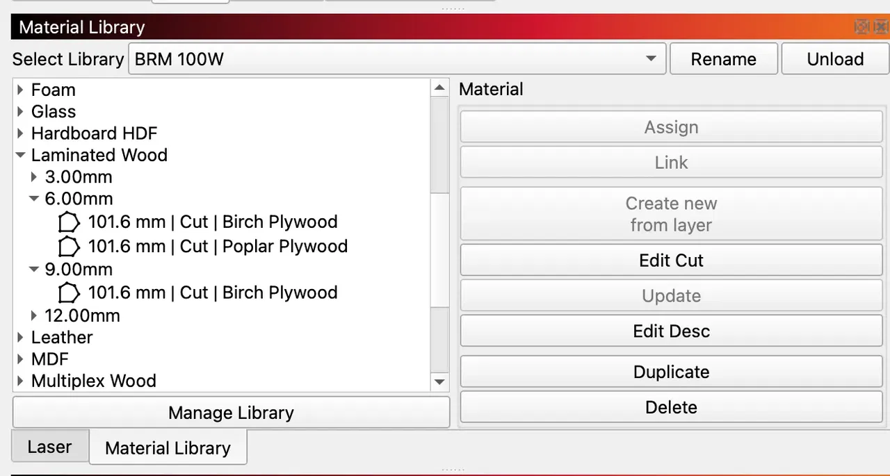
## Understanding the library structure
[Section titled “Understanding the library structure”](#understanding-the-library-structure)
The library is organised in three levels:
1. **Material class** (e.g. Laminated Wood)
2. **Thickness** (e.g. 3.00 mm)
3. **Parameter sets**, named in the format: `[preferred lens] | [machining method] | [material-specific name]`
Example:
* Laminated Wood
* 3.00 mm
* 63.5 mm | Cut | Poplar Plywood
* 6.00 mm
* 101.6 mm | Cut | Birch Plywood
* 101.6 mm | Cut | Poplar Plywood
The lens distance (63.5 mm, 101.6 mm, etc.) tells you which focus lens the parameters were tuned for. Using a different lens will affect the result.
## Step 4: Apply a material to a layer
[Section titled “Step 4: Apply a material to a layer”](#step-4-apply-a-material-to-a-layer)
There are two ways to apply a material from the library to a layer: **Assign** and **Link**. Both start the same way.
1. In the **Cuts / Layers** window, click the layer you want to set up.
2. In the **Material Library** panel, click the material that matches your job.
3. On the right side of the panel, click either **Assign** or **Link**.
### Assign vs. Link, what’s the difference?
[Section titled “Assign vs. Link, what’s the difference?”](#assign-vs-link-whats-the-difference)
| Action | What it does | When to use it |
| ---------- | ------------------------------------------------------------------------------------- | -------------------------------------------------------------------------------------------------------- |
| **Assign** | Copies the parameter values into your layer. Changes on either side stay independent. | One-off jobs, or when you want to tweak parameters for this specific file without affecting the library. |
| **Link** | Connects the layer to the library entry. Changes on either side stay in sync. | Recurring jobs where you want the layer to always reflect the latest library values. |
## Troubleshooting
[Section titled “Troubleshooting”](#troubleshooting)
* **The library doesn’t show any materials after loading.**\
Make sure you selected a `.clb` file, not the folder. Try clicking **Manage Library** → **Load library** again.
* **My laser source wattage isn’t in the file list.**\
The library currently ships for 100 W, 150 W, and 300 W CO₂ sources. If your machine sits between two of these, start from the closest lower wattage and verify on a test piece before running the full job.
* **The cut quality is off, even with library settings.**\
Library values assume the listed lens and a properly aligned, clean machine. Check the lens distance in the parameter set name, verify mirror alignment, and confirm the material matches the entry (e.g. poplar plywood vs. birch plywood behave differently).
## Need help?
[Section titled “Need help?”](#need-help)
If something doesn’t work as expected, contact BRM support by clicking this [link](/en/contact) with your machine model, laser source wattage, the material entry you used, and a photo of the result.
# Peripherals
### Airsupply
***
[Compressor optionCompressor option](/en/peripherals/air-supply/compressor-option)
[>](/en/peripherals/air-supply/compressor-option)
[How does the air supply work on my Pro laser machine?How does the air supply work on my Pro laser machine?](/en/peripherals/air-supply/how-does-the-air-supply-work-on-my-brm-pro)
[>](/en/peripherals/air-supply/how-does-the-air-supply-work-on-my-brm-pro)
[How does the standard air pump included with the BRM Budget work?You will receive a small air pump with the BRM Budget.](/en/peripherals/air-supply/how-does-the-supplied-air-pump-work-with-the-brm-budget)
[>](/en/peripherals/air-supply/how-does-the-supplied-air-pump-work-with-the-brm-budget)
[How does the standard air pump supplied with the BRM Original work?A small air pump is included with the BRM Original.](/en/peripherals/air-supply/how-does-the-supplied-air-pump-work-with-the-brm-original)
[>](/en/peripherals/air-supply/how-does-the-supplied-air-pump-work-with-the-brm-original)
[How does the standard air pump included with the BRM Slim work?You will receive a small air pump with the BRM Slim.](/en/peripherals/air-supply/how-does-the-supplied-air-pump-work-with-the-brm-slim)
[>](/en/peripherals/air-supply/how-does-the-supplied-air-pump-work-with-the-brm-slim)
### BRM Extractor
***
[Why and how to create a BRM Extractor LOG file?When you have a BRM Extractor it can happen that there is a problem of which you do not immediately know the cause. Then it can be useful to create a LOG file.](/en/peripherals/brm-extractor/why-and-how-do-i-create-a-brm-extractor-log-file)
[>](/en/peripherals/brm-extractor/why-and-how-do-i-create-a-brm-extractor-log-file)
### Rotation
***
[Using the BRM Original RotationIf you have a BRM Original then you received a claw rotation with the machine. In the video below you can see how to install and use the rotation.](/en/peripherals/rotation/explanation-video-rotation-unit-brm-original)
[>](/en/peripherals/rotation/explanation-video-rotation-unit-brm-original)
[How do I set up my roller rotary?When you want to use the Pro with the roller rotary, there are a number of steps you need to follow.](/en/peripherals/rotation/roller-rotation-unit-brm-pro-and-slim)
[>](/en/peripherals/rotation/roller-rotation-unit-brm-pro-and-slim)
### Waterchiller
***
[My CW-3000 water chiller goes into alarm, what to do?My CW-3000 water chiller goes into alarm, what to do?](/en/peripherals/water-chiller/alarmcw-3000)
[>](/en/peripherals/water-chiller/alarmcw-3000)
[My CW-5000 / CW-5200 water chiller goes into alarm, what to doMy CW-5000 / CW-5200 water chiller goes into alarm, what to do](/en/peripherals/water-chiller/alarmcw-5000)
[>](/en/peripherals/water-chiller/alarmcw-5000)
[The water chiller in top conditionAll the important everyday knowledge about the water chiller to keep it in good condition so your laser source stays in top condition too!](/en/peripherals/water-chiller/the-water-chiller-in-top-condition)
[>](/en/peripherals/water-chiller/the-water-chiller-in-top-condition)
# Compressor option
> Compressor option
A compressor option allows you to add more air while cutting. This can be useful when cutting wood and other materials. You can cut thicker materials faster.
## [BRM Original](https://www.brmlasers.com/product/pro-1300?utm-source=support-site) and [BRM Slim](https://www.brmlasers.com/product/slim-1300?utm-source=support-site)
[Section titled “BRM Original and BRM Slim”](#brm-original-and-brm-slim)
A compressor option allows you to cut thicker materials faster. Also, the cutting line is, for example, better with wood. The compressor option is an optional feature, and can be added to your [BRM Original](https://www.brmlasers.com/product/pro-1300?utm-source=support-site) and [BRM Slim](https://www.brmlasers.com/product/slim-1300?utm-source=support-site). Should you wish to receive more information about the compressor option on your BRM Original or BRM Slim, please send a [ticket](/en/contact).
## [BRM Pro](https://www.brmlasers.com/product/pro-1300?utm-source=support-site)
[Section titled “BRM Pro”](#brm-pro)
The [BRM Pro](https://www.brmlasers.com/product/pro-1300?utm-source=support-site) has a compressor option built in as standard. The machine does not come with a compressor but with a standard air pump. Should you want to work with a compressor you will have to purchase your own.
# How does the air supply work on my Pro laser machine?
> How does the air supply work on my Pro laser machine?
Air supply guide for the [BRM Pro](https://www.brmlasers.com/product/pro-1300?utm-source=support-site) laser machine.
The [Pro](https://www.brmlasers.com/product/pro-1300?utm-source=support-site) laser machine includes a compressor connection as standard. The advantage of the compressor connection and using a compressor is that the air is buffered. That ensures a constant flow of air instead of it coming out of the nozzle in pulses. It also gives you more control over the air pressure, allowing you to use higher pressure which in turn can help cut thicker materials.
The compressor connection does not have a flow controller to regulate the liters per minute but a pressure regulator to regulate the pressure. On the right side of the machine, there is a rotary knob with which you can regulate the pressure.
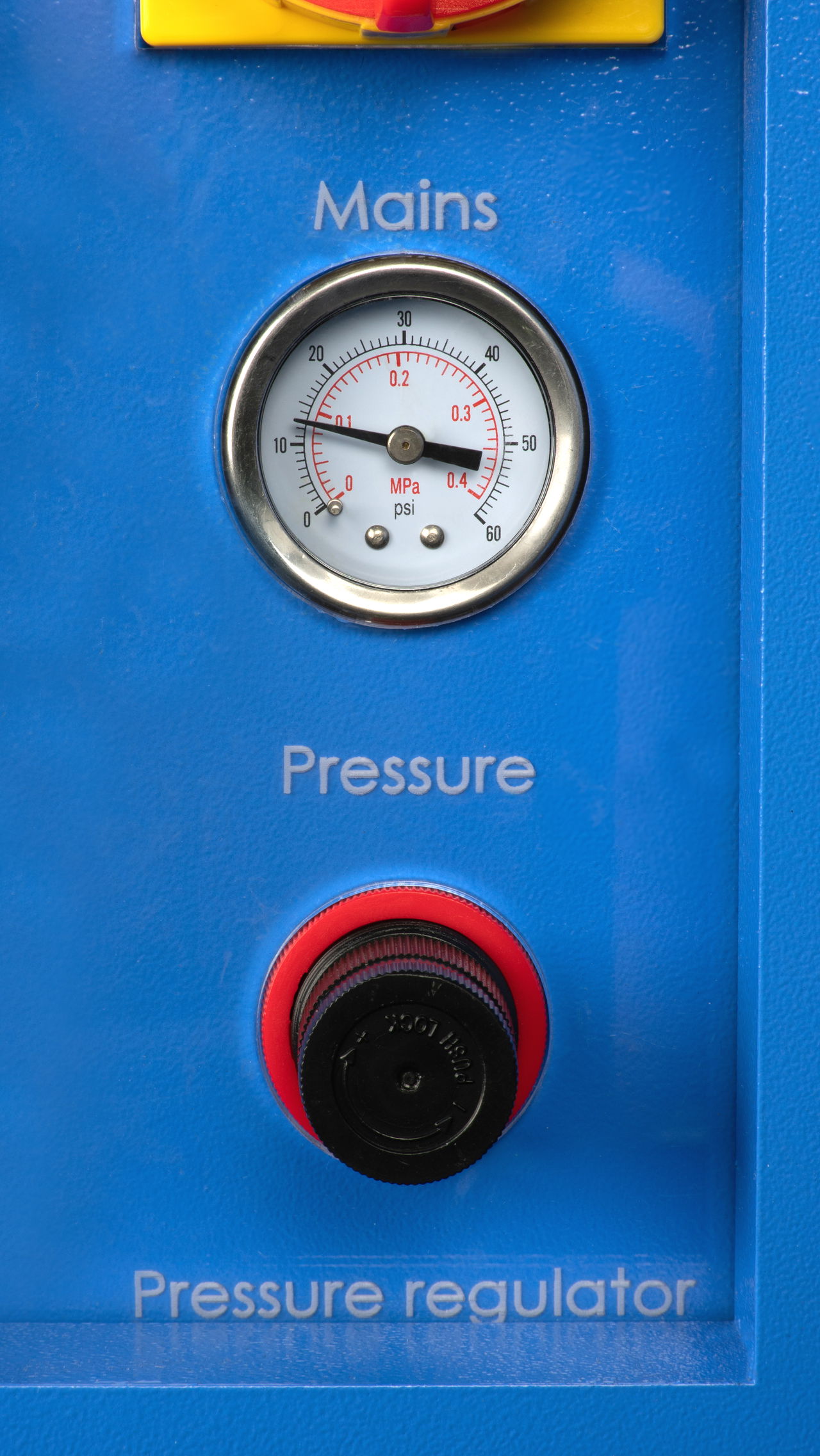
You can turn the knob left and right. When you press the knob, it is locked. If the knob does not turn, you need to pull out the knob to release the lock. Above the knob, you will see a pressure gauge with a dial. It shows how much pressure there is. The input pressure from the compressor to the laser machine must be below 8 bar. That is more than enough, often you use a lot less than that. If you do put more than 8 bars into the machine, the components involved in the compressor connection can break down.
You can adjust the air pressure as soon as the machine starts a program. When the machine is off, the air pressure will not decrease because the valve is closed and the pressure cannot release itself.
0.1 to 0.5 bar air gives the best results when engraving. For cutting thick wood, for example, you can use around 2 bars.
It is important to keep the air slightly open at all times. If you do not add air, smoke and dust will settle on the lens. This increases the chance of the lens breaking or burning, making it unusable. When the machine is on pause or not cutting / engraving, the air will be off, so no air is wasted.
## No air is coming out of the nozzle, now what?
[Section titled “No air is coming out of the nozzle, now what?”](#no-air-is-coming-out-of-the-nozzle-now-what)
If the airflow from the nozzle is less than usual, the filter in the air care unit may be saturated or it may be full of water. When it is full of water, the air cannot pass through it and will not reach the nozzle.
On the right side of the machine is the electrical cabinet. In there you will find the air care unit. There is a hole in the bottom of the electrical cabinet and the bottom of the air care unit is sticking through this hole. Locate the hole and the bottom of the air care unit. Fit a dish or a small cup under it. You can now drain the water by pressing the tip at the bottom of the air care unit. The water will now flow into the dish or cup.
Make sure the laser machine and compressor are off. If there is air pressure, the water can’t be drained because the tip of the unit can’t be pressed.
All the dirt in the air is either in the water or in the filter in the air care unit. When you drain the water, you also drain the dirt that is in it.
Also, check whether the air in the software is switched on. You can see this in the LightBurn software at your layer. Make sure the slider is green.
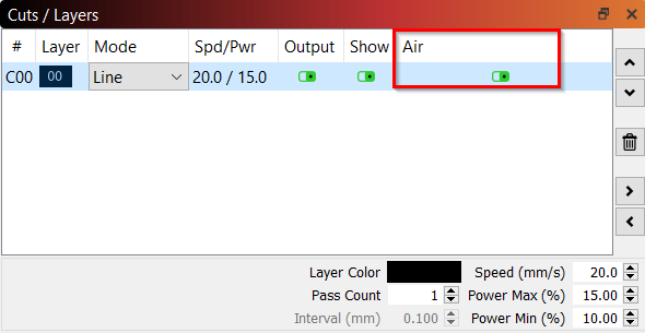
If it is set correctly, check the pointer in the pressure gauge above the pressure regulator. See if you can add more air by rotating it.
Should that not work, check whether the compressor is switched on and is not empty. If all this is also correct, the next step is to see if there is a kink in the air hose preventing the air from passing through.
## I am going to buy a compressor, which requirements should it meet?
[Section titled “I am going to buy a compressor, which requirements should it meet?”](#i-am-going-to-buy-a-compressor-which-requirements-should-it-meet)
The compressor must meet a certain liters-per-minute requirement, preferably at least 120 L/min. The compressor is allowed to supply 8 bar. If, for example, the compressor can do 10 bar, then a pressure regulator needs to be placed between the compressor and the machine to reduce the 10 bar to a maximum of 8 bar.
Also, it is useful to choose a compressor with a larger buffer tank so it will not switch on all the time. Make sure that it is designed to deliver 120 L/min, for example, 8 hours a day. This can often be found in the Data Sheet of the compressor. If you can’t find it there, it’s best to ask the seller of the compressor for these specifications.
We supply the machine with an 8 mm push-in fitting and a piece of air hose. From the connection with the machine up to the compressor, you are responsible for buying the right parts.
If you have any further questions, please feel free to submit a [ticket](/en/contact).
# How does the standard air pump included with the BRM Budget work?
> You will receive a small air pump with the BRM Budget.
Air pump guide for the [BRM Budget](https://www.brmlasers.com/product/slim-1300?utm-source=support-site).
## Supplied air pump
[Section titled “Supplied air pump”](#supplied-air-pump)
A small air pump is supplied with the [BRM Budget](https://www.brmlasers.com/product/slim-1300?utm-source=support-site). It provides approximately 0.1 bar of pressure. You connect the air pump to the back of the laser machine, both the air hose and the power plug. In the machine, the air hose goes to the right side of the machine. This is where you will find a bolt on the outside. It is connected to an air regulator. The air hose is connected to the air regulator. From the air regulator, the air hose goes via the Y- and X-axis to the air coupling that is attached to the nozzle.
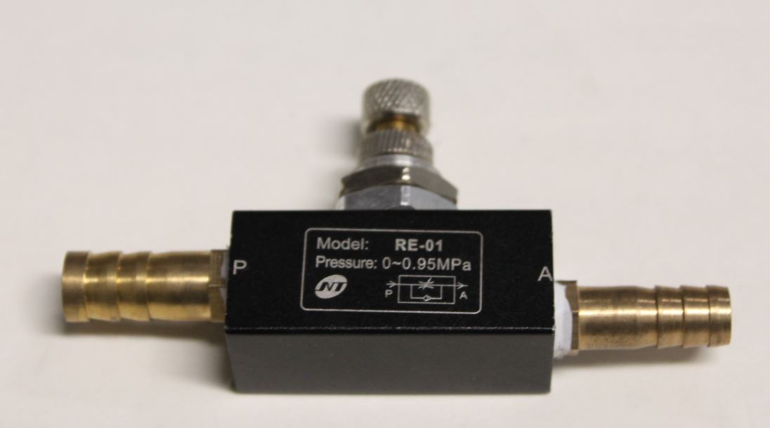
The air regulator has a flow valve with which you can adjust the number of liters per minute. By turning the bolt on the right side of the machine that goes to the air regulator, you can add more or less air.
## Should I always add air?
[Section titled “Should I always add air?”](#should-i-always-add-air)
Some materials improve when you add a little more air, whereas other materials require less air. However, it is important to always add some air. If you fail to do so, smoke can settle on the lens. Then dirt will remain on it. If you start cutting or engraving again, you can burn the dirt into the lens, making the lens unusable. The lens must then be replaced to be able to cut or engrave properly again.
If you often add relatively small amounts of air, you should check the lens more often to see if it is still clean and clean it more often if necessary.
Click [here](/en/maintenance/optical-path/lens-cleaning) to read an article on cleaning the lens.
## Hardly any air comes out of the nozzle, now what?
[Section titled “Hardly any air comes out of the nozzle, now what?”](#hardly-any-air-comes-out-of-the-nozzle-now-what)
If there is less air than you expected, you can check whether you have opened the flow valve properly. Open it if it isn’t opened properly.
Inside the air regulator, there is a small piece of mesh. You can remove the hoses from the air regulator. In one of the connections, you will find this piece of mesh. Some dirt may have accumulated on it, preventing the air from flowing through it. You can use a needle or something similar to remove the dirt.
It can be a bit tricky to reach the mesh. If you need to remove the air regulator from the machine, you must mark which hose is on which side of the air regulator so you can reconnect the air regulator correctly. You can unscrew the nut on the outside of the machine to loosen the air regulator.
Removal of the mesh from the air regulator allows the dirt to pass through the air hoses freely. This allows the dirt to easily reach the lens and this can cause the lens to wear out faster. We, therefore, do not recommend removing the mesh. However, if you do remove the mesh, make sure to check and clean the lens more often.
## Is it possible to connect a compressor to the [BRM Budget](https://www.brmlasers.com/product/slim-1300?utm-source=support-site) without adjusting anything?
[Section titled “Is it possible to connect a compressor to the BRM Budget without adjusting anything?”](#is-it-possible-to-connect-a-compressor-to-the-brm-budget-without-adjusting-anything)
No, you cannot just connect a compressor to the air supply. The hoses in the machine are not made for the pressure that a compressor provides. The hoses can handle about 0.5 bar, if you apply more pressure the hoses will break. Also, the airflow will remain continuous, because there is no valve on the machine that closes when you are not working. Because of that, your compressor will run empty very quickly. Should you wish to work with a compressor, please submit a [ticket](/en/contact) and we will help you.
# How does the standard air pump supplied with the BRM Original work?
> A small air pump is included with the BRM Original.
Air pump guide for the [BRM Original](https://www.brmlasers.com/product/pro-1300?utm-source=support-site).
## Supplied air pump
[Section titled “Supplied air pump”](#supplied-air-pump)
A small air pump is supplied with the [BRM Original](https://www.brmlasers.com/product/pro-1300?utm-source=support-site). It provides approximately 0.1 bar of pressure. You connect this air pump to the back of the laser machine, both the air hose and the power plug. Then the air hose is connected from the back of the machine via the Y- and X-axis to the laser head. The air hose is connected to the nozzle mount in an air coupling. The air coupling has a flow controller with which you can adjust the number of liters per minute. By turning the bolt on the air coupling, you can adjust the airflow.
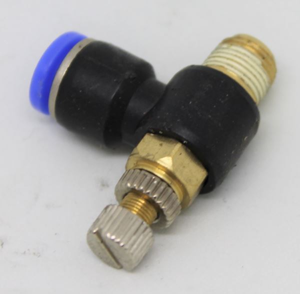
## Should I always add air?
[Section titled “Should I always add air?”](#should-i-always-add-air)
Some materials improve when you add a little more air, whereas other materials require less air. However, it is important to always add some air. If you fail to do so, smoke can settle on the lens. Then dirt will remain on the lens. If you start cutting or engraving again, you can burn the dirt into the lens, making it unusable. The lens must then be replaced to be able to cut or engrave properly again.
If you often add relatively small amounts of air, you should check the lens more often to see if it is still clean and clean it more often if necessary.
Click [here](/en/maintenance/optical-path/lens-cleaning) to read an article on cleaning the lens.
## Hardly any air comes out of the nozzle, now what?
[Section titled “Hardly any air comes out of the nozzle, now what?”](#hardly-any-air-comes-out-of-the-nozzle-now-what)
If there is less air than you expected, you can check whether you have opened the flow controller properly. See what happens if you turn the bolt.
In the air coupling is a small disc with some small holes in it. Unscrew the air coupling from the nozzle mount and check whether the holes are still completely open. If they are not or only partly open, you can pierce them with a needle or something similar.
Also, the hole in the nozzle may have become a little smaller due to deposit. Check whether this is the case and clean if necessary.
## Is it possible to connect a compressor to the [BRM Original](https://www.brmlasers.com/product/pro-1300?utm-source=support-site) without adjusting anything?
[Section titled “Is it possible to connect a compressor to the BRM Original without adjusting anything?”](#is-it-possible-to-connect-a-compressor-to-the-brm-original-without-adjusting-anything)
No, you cannot just connect a compressor to the laser machine. The hoses in the machine are not made for the pressure that a compressor provides. The hoses can handle about 0.5 bar, if you apply more the hoses will break. Also, the airflow will remain continuous, because there is no valve on the machine that closes when you are not working. Because of that, your compressor will run empty very quickly.
Should you wish to work with a compressor, please submit a [ticket](/en/contact) and we will help you.
# How does the standard air pump included with the BRM Slim work?
> You will receive a small air pump with the BRM Slim.
Air pump guide for the [BRM Slim](https://www.brmlasers.com/product/slim-1300?utm-source=support-site).
## Supplied air pump
[Section titled “Supplied air pump”](#supplied-air-pump)
A small air pump is supplied with the [BRM Slim](https://www.brmlasers.com/product/slim-1300?utm-source=support-site). It provides approximately 0.1 bar of pressure. You connect this air pump to the back of the laser machine, both the air hose and power plug. Inside the machine, the air hose is connected from the back of the machine to the right side of the machine. This is where you will find a bolt on the outside. It is connected to an air regulator. The air hose is also connected to the air regulator. From the air regulator, the air hose goes via the Y- and X-axes to the air coupling that is attached to the nozzle.

The air regulator has a flow controller with which you can adjust the amount of liters per minute. By turning the knob on the right side of the machine that goes to the air regulator, you can add more or less air.
## Should I always add air?
[Section titled “Should I always add air?”](#should-i-always-add-air)
Some materials improve when you add a little more air, whereas other materials require less air. However, it is important to always add some air. If you fail to do so, smoke can settle on the lens. Then dirt will remain on it. If you start cutting or engraving again, you can burn the dirt into the lens, making the lens unusable. The lens must then be replaced to be able to cut or engrave properly again.
If you often add relatively small amounts of air, you should check the lens more often to see if it is still clean and clean it more often if necessary.
Click [here](/en/maintenance/optical-path/lens-cleaning) to read an article on cleaning the lens.
## Hardly any air comes out of the nozzle, now what?
[Section titled “Hardly any air comes out of the nozzle, now what?”](#hardly-any-air-comes-out-of-the-nozzle-now-what)
If there is less air than you expected, you can check whether you have opened the flow controller properly. Try adjusting the knob and see what happens.
Inside the air regulator, there is a small piece of mesh. You can remove the hoses from the air regulator. In one of the connections, you will find this piece of mesh. Some dirt may have accumulated on it, preventing the air from flowing through it. You can use a needle or something like it to remove the dirt.
The mesh can be a bit tricky to reach. If you need to remove the air regulator from the machine, you must mark which hose is on which side of the air regulator so you can reconnect the air regulator correctly. You can unscrew the nut on the outside of the machine to loosen the air regulator.
Removal of the mesh from the air regulator allows the dirt to pass through the air hoses freely. This allows the dirt to easily reach the lens and this can cause the lens to wear out faster. We, therefore, do not recommend removing the mesh. If you do remove the mesh, make sure to check and clean the lens more often to prevent dirt burning into the lens.
## Is it possible to connect a compressor to the [BRM Slim](https://www.brmlasers.com/product/slim-1300?utm-source=support-site) without adjusting anything?
[Section titled “Is it possible to connect a compressor to the BRM Slim without adjusting anything?”](#is-it-possible-to-connect-a-compressor-to-the-brm-slim-without-adjusting-anything)
No, you cannot just connect a compressor to the air supply. The hoses in the machine are not made for the pressure that a compressor provides. The hoses can handle about 0.5 bar, if you apply more pressure the hoses will break. Also, the airflow will remain continuous, because there is no valve on the machine that closes when you are not working. Because of that, your compressor will run empty very quickly.
Should you wish to work with a compressor, please submit a [ticket](/en/contact) and we will help you.
# Why and how to create a BRM Extractor LOG file?
> When you have a BRM Extractor it can happen that there is a problem of which you do not immediately know the cause. Then it can be useful to create a LOG file.
## How to create a LOG file
[Section titled “How to create a LOG file”](#how-to-create-a-log-file)
When using a BRM Extractor, you may encounter a problem of which you do not immediately know the cause. In that case, it may be helpful to create a LOG file and mail it to us to see if we can find the cause of the problem.
Unfortunately, not all BRM extractors allow you to create a LOG file. If you are not sure whether your BRM Extractor enables this, please open the door on the front of the Extractor. If there is an opening above the filters where a USB stick can be plugged in, it is possible to create a LOG file. It might also be that the USB port on the BRM Extractor L / XL / XXL is on its right-hand side of the extractor.
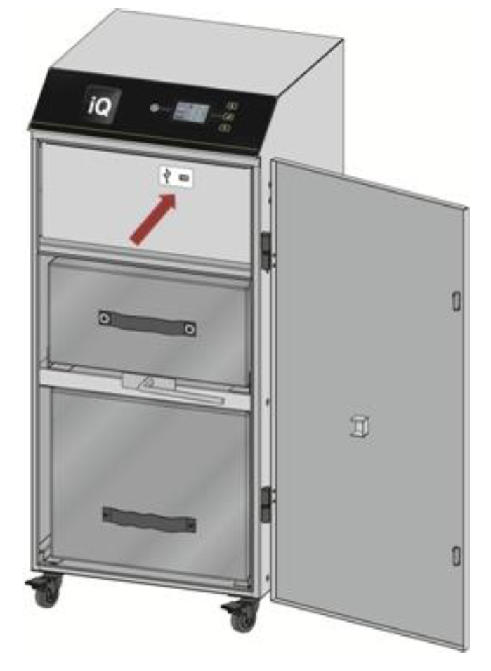
## Please follow the instructions below to create a LOG
[Section titled “Please follow the instructions below to create a LOG”](#please-follow-the-instructions-below-to-create-a-log)
Please take a USB stick. It should be able to hold a maximum of 8 GB. The USB stick also needs to be empty and formatted (FAT32). Make sure the BRM Extractor is on Stand-by. The power button on the display lights up red.
Open the door of the BRM Extractor and place the USB stick in the designated opening. If the USB port is on the side of the Extractor, you can remove the silicon dust cap and insert the USB stick.
The LCD display shows the icon below. Click on the corresponding button next to the word “DOWNLOAD”.
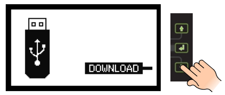
The display shows a progress bar.
As soon as a check mark appears on the display, the download is successful which means you can remove the USB stick.

If a triangle with an exclamation mark appears on the display, the download has failed. Check whether your USB stick can hold a maximum of 8 GB and whether the formatting was successful. If all these things are ok, please try another USB stick with the same specifications.

Once you have successfully created a LOG file, you can send it to BRM Lasers via . Two files have been created, both are needed to be able to extract what is needed. Also, send a picture of the type plate of the BRM Extractor along with a problem specification so we have a complete description.
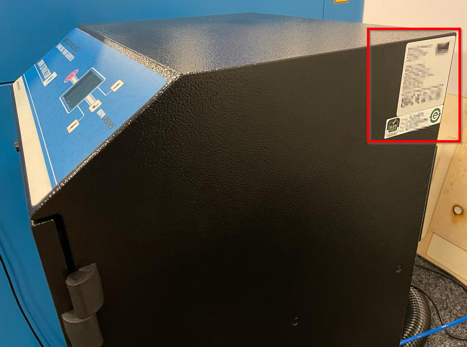
# Using the BRM Original Rotation
> If you have a BRM Original then you received a claw rotation with the machine. In the video below you can see how to install and use the rotation.
Rotation guide for the [BRM Original](https://www.brmlasers.com/product/pro-1300?utm-source=support-site).
When you own a [BRM Original](https://www.brmlasers.com/product/pro-1300?utm-source=support-site), you have received a chuck rotation with the machine. In the video below you can see how to install and use the rotation.
## Instruction video
[Section titled “Instruction video”](#instruction-video)
In case you have additional questions you can always send us a [ticket](/en/contact).
# How do I set up my roller rotary?
> When you want to use the Pro with the roller rotary, there are a number of steps you need to follow.
The roller rotary makes it possible to engrave round objects such as glasses and bottles, or to cut plastic tubes. The video below walks you through the process step by step.
## Setting up the roller rotary
[Section titled “Setting up the roller rotary”](#setting-up-the-roller-rotary)
1. Turn off the machine or activate the emergency stop.
2. Place the rotary in the work area.
3. Connect the rotary using the connector on the right side panel, near the door opening.
4. Turn the machine back on, or release the emergency stop.
5. Press the reset button to release the machine.
6. Wait until the machine has completed its homing cycle. This takes longer than usual due to a required timeout on the Y-axis.
The machine now switches the Y-axis over to the rotary. The Y-axis is then unpowered and must be moved manually to the desired position.
7. Slide the Y-axis forward and look along the X-rail towards the rotary. Adjust the rotary until it runs parallel to the X-rail.
8. Use the adjustment options on the rotary to get the engraving surface of the product as level as possible.
9. Position the laser head centered above the rotary.
## Settings in LightBurn
[Section titled “Settings in LightBurn”](#settings-in-lightburn)
Tip
Set the job origin to center. This makes alignment on round objects a lot easier.
10. Open the rotary settings via **Laser Tools > Rotary Setup**.
11. Select **Roller** as the rotary type.
12. Enable **Enable Rotary**.
13. Check the direction of the rotary motor. The cable exit indicates the motor side. If the cable points to the right (blue side of the machine), enable **Mirror Output**.
14. Set **Steps per Rotation** to **16666**.
15. Set **Roller Diameter** to **80** mm.
Note
The machine may show a “Y/U Slop over” error. Move the Y-axis or U-axis a small step forward (arrow-down button) to give the software some virtual clearance. The Y-axis does not physically move, but the software requires this margin. This is a known issue in the software.
16. Engrave your product.
## Stopping use of the roller rotary
[Section titled “Stopping use of the roller rotary”](#stopping-use-of-the-roller-rotary)
Note
The machine remembers the rotary settings even after being turned off. Disable the rotary immediately after use so you don’t forget at the start of your next session.
1. Turn off the machine or activate the emergency stop.
2. Disconnect the rotary connector from the machine.
3. Remove the rotary from the work area.
4. Open the rotary settings via **Laser Tools > Rotary Setup**.
5. Disable the rotary.
6. Check the status bar at the bottom of LightBurn and verify that **“Rotary Enabled”** is no longer displayed.
In case you have additional questions you can always send us a [ticket](/en/contact).
# My CW-3000 water chiller goes into alarm, what to do?
> My CW-3000 water chiller goes into alarm, what to do?
## Why does the CW-3000 water chiller raise an alarm?
[Section titled “Why does the CW-3000 water chiller raise an alarm?”](#why-does-the-cw-3000-water-chiller-raise-an-alarm)
The CW-3000 is a water chiller that cools the water by releasing the heat to the environment through a fan.
When the CW-3000 is in alarm, its cooling capacity may not be sufficient for the environmental temperature. The CW-3000 only emits heat to its surrounding area. When the environmental temperature is too high, the water chiller cannot release the heat to the area, so its water will remain warm and the temperature will increase.
The water chiller can release about 5 to 7 degrees of heat to the area around it. If, for example, the surrounding temperature is 20 degrees, the water temperature can become approximately 25 degrees. The temperature limit of the chiller is approximately 28 degrees, which means that the temperature in the room where the chiller is located should not exceed 23 degrees. When the temperature in the surrounding area exceeds 23 degrees, the chiller will go into alarm because the water heats up too much and the heat can’t dissipate.
When this happens, you need to make sure that the temperature in the room is brought down. You could also pause working for a while. The water temperature will drop, allowing you to continue working for a while.
If the temperature on the chiller suddenly rises very quickly, it might be that it can no longer dissipate its heat into the surroundings. There is a fan at the back of the chiller, Check if this is free of dust and whether it works. If you see that a lot of dust has built up you can turn off the water chiller for a while and remove the dust. The fan will be off so you can’t get caught.
In addition, there are slots located on the side of the chiller. Check whether these are dust-free. Clean them if you notice any dust. Be sure to turn off the chiller when doing this.
Also, make sure there is enough space around the chiller. The chiller sucks in fresh air and releases warm air. If the chiller is in a tight space, there is less fresh air and it will suck in the warm air, that it is releasing. This does not help to bring the temperature down.
The water chiller must not be placed in a room where it can freeze. When it freezes, the water in the water chiller will freeze. This will damage the water chiller and break the laser source.
Apart from that, the CW-3000 water chiller measures if there is circulation. When there is no circulation, the CW-3000 water chiller will raise an alarm.
There are several reasons why there is no water circulation. Water cannot circulate if one of the hoses is kinked. Check that all hoses are kink-free.
## Dirt
[Section titled “Dirt”](#dirt)
There may also be dirt in the cooling water. If, for example, it contains algae, this can clot and cause a blockage. The water will also retain the heat better and the temperature of the water will rise. Take the following action if this occurs.
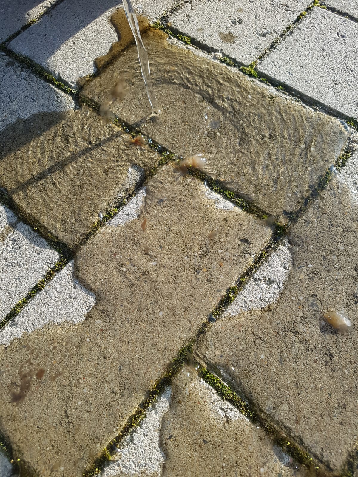
Turn the laser machine off. Plug the water chiller into a socket that is not connected to the laser machine. Remove the water from the laser source and empty the water chiller. Fill the water chiller with about 2 L of demineralized water. Switch on the water chiller for a few hours so the laser source will rinse clean. Leave the laser machine switched off.
Remove the water from the laser source after a few hours and empty the water chiller. Then fill the water chiller with demineralized water. Read the following article to make sure everything is done correctly, and you will not damage the laser source: [The water chiller in top condition.](/en/peripherals/water-chiller/the-water-chiller-in-top-condition)
## Water level
[Section titled “Water level”](#water-level)
Please also check whether there is an adequate amount of water in the chiller. If a lot of water is suddenly lost, check whether there is any water in the outer glass tube of the laser source. The laser source consists of 3 glass tubes. The large outer tube should not contain any water. If it does, the laser source will need to be replaced.
Also, check if you see a puddle of water somewhere. If you notice that, check whether all the water hoses are still attached. If one of the water hoses has come loose, fix it. Over time, a water hose can also become somewhat porous. You can order new hoses if this is the case.
If there are no kinks in the hose, the water is clean and there is sufficient water, then the chiller’s pump may be defective.
If the mentioned tips do not solve the problem, please submit a [ticket](/en/contact).
# My CW-5000 / CW-5200 water chiller goes into alarm, what to do
> My CW-5000 / CW-5200 water chiller goes into alarm, what to do
## Why does the CW-5000 / CW-5200 water chiller raise an alarm?
[Section titled “Why does the CW-5000 / CW-5200 water chiller raise an alarm?”](#why-does-the-cw-5000--cw-5200-water-chiller-raise-an-alarm)
The CW-5000 and CW-5200 water chillers have an active cooling system. That means there is a heat exchanger in the water chiller, just like in a refrigerator. The heat from the laser source is transferred to the heat exchanger. The heat exchanger then dissipates the heat into the surrounding air.
Because of its heat exchanger, the surrounding temperature can be a little higher, up to 35 degrees. You can therefore also use the chiller in a slightly warmer room. It cools actively and can therefore also cool below the surrounding temperature.
If the water chiller does not cool properly and the temperature keeps rising, it may well be that the gas in the chiller is running out. It might also be the case that the chiller does not reach a certain lower temperature anymore. That is also an indication the gas mixture is running out.
Unfortunately, it is not possible to refill the gas. When it runs out of gas, the whole chiller needs to be replaced.
When the temperature rises and reaches a certain temperature, around 30 degrees Celsius, the chiller will raise an alarm. On the display, you can then see that the temperature is (too) high and that this is the cause of the alarm.
The chiller is designed to be on 24/7, with a running laser machine, and still maintain the temperature. When an alarm is raised thanks to an excessive temperature, it is often a sign of a defective heat exchanger. Another case might be that the room in which the chiller is located is too warm after all, exceeding a temperature of 35 degrees. Bear in mind that the laser machine and water chiller itself also contribute to a higher room temperature.
## Dirt
[Section titled “Dirt”](#dirt)
On the sides of the water chiller are grids with a filter. These grids and filters are used to draw the fresh air in and filter it. The grids can be clicked off easily. At the back of the grid is a filter. It may get clogged, so it has to be checked regularly and cleaned if necessary. On the back of the chiller, are 2 fans. Clean these regularly as well. Please switch off the chiller when cleaning to avoid any risk of getting caught in the fans.
Periodically check that the fans at the back of the chiller are still running. If one or both fans have stopped working, they will have to be replaced.
The water chiller should not be placed in a room where it may freeze. When it freezes, the cooling water in the chiller will frost and damage the water chiller. The laser source will also break and needs to be replaced.
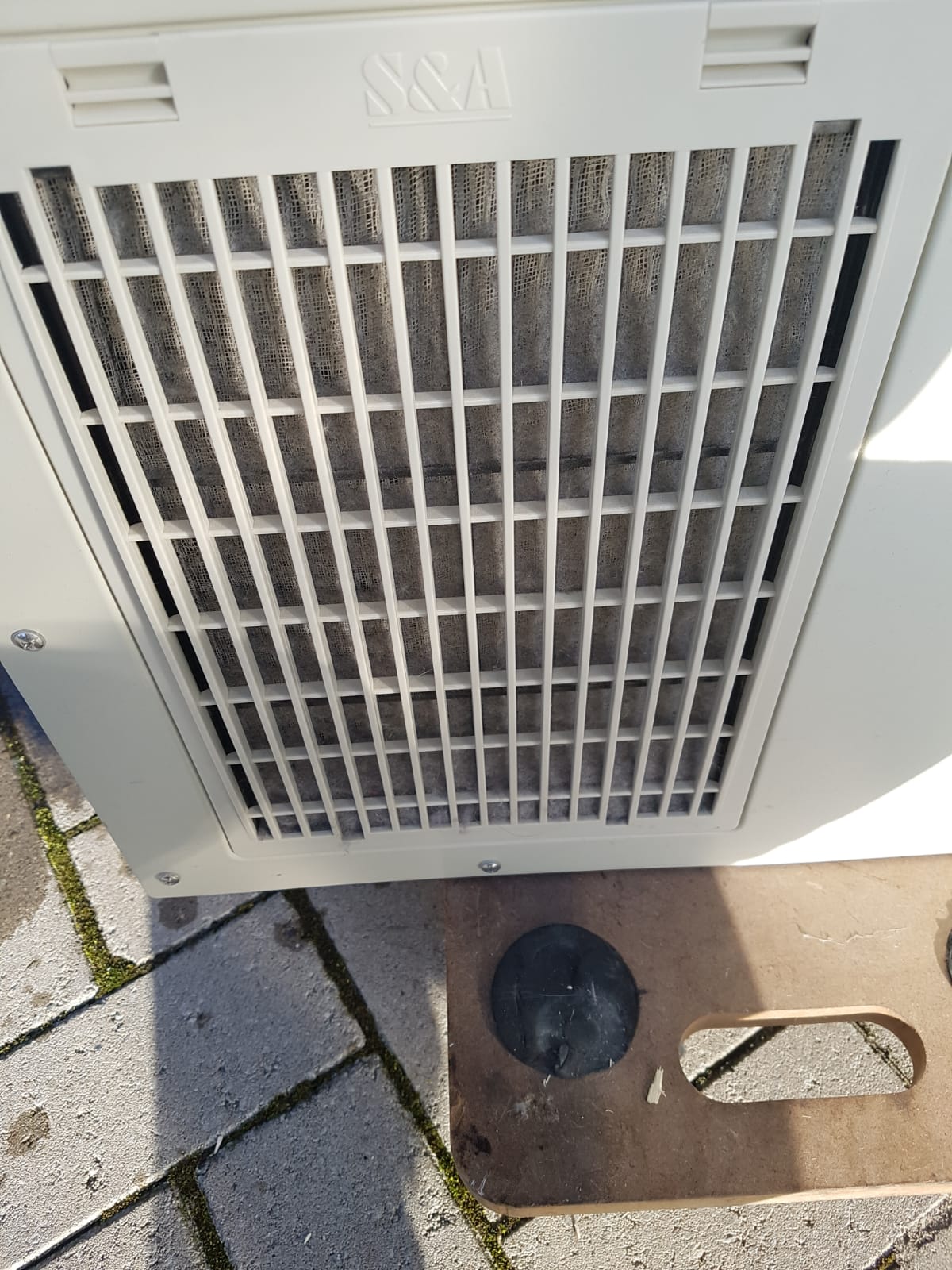
There may be dirt in the cooling water. If, for example, it contains algae, this can clot and cause a blockage. The water will also retain the heat better and the temperature of the water will rise. Take the following action if this occurs.
Turn the laser machine off. Plug the water chiller into a socket that is not connected to the laser machine. Remove the water from the laser source and empty the water chiller. Fill the water chiller with about 2 L of demineralized water. Switch on the water chiller for a few hours so the laser source will rinse clean. Leave the laser machine switched off.
Remove the water from the laser source after a few hours and empty the water chiller. Then fill the water chiller with demineralized water. Read the following article to make sure everything is done correctly, and you will not damage the laser source: [The water chiller in top condition](/en/peripherals/water-chiller/the-water-chiller-in-top-condition)
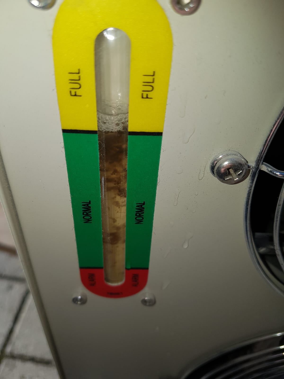
## Flow
[Section titled “Flow”](#flow)
The CW-5000 and CW-5200 water chillers have a flow meter. It can detect when there is less flow than usual. When less flow is detected, the chiller will raise an alarm and switch off the pump etc. to avoid the pump being damaged. Without flow, the pump will switch off as well. If this occurs, it might be that there is not enough water in the chiller. At the back of the chiller, there is a water level gauge. Check if the water level is still in the green section. If this is not the case, check whether there is a puddle of water somewhere and whether both hoses from the chiller to the machine are still attached correctly and did not become porous. If you do not notice water anywhere, inspect the laser source. It consists of 3 glass tubes. Check if there is water in the large outer tube. If so, the laser source will need to be replaced.
At the back of the water chiller, there is a grey cap, which is for draining the chiller. Check whether this cap is fitted tightly. Make sure that all the hoses are free and that there are no kinks in them. If a hose is kinked, water cannot circulate and an alarm will sound. Should you see a kink in a hose, please correct it.
If there is no puddle of water anywhere and the outer laser tube is free of water but there is still not enough water in the chiller, you can add some water. Read more [here](/en/peripherals/water-chiller/the-water-chiller-in-top-condition).
If you turn the water chiller on but the display and the lights on the front of it do not work, the power supply of the water chiller may be defective. If the display does not switch on but the lights on the front of the chiller do and optionally the alarm is activated, then the display is probably defective.
When you start up the water chiller but it does not switch on, the first thing to check is whether the plug is connected to the wall socket and the chiller. If it is connected properly and there is power in the socket, the fuse in the water chiller might be defective. Look for a cause somewhere, such as a water leak causing a short circuit.
If the mentioned tips do not solve the problem, please submit a [ticket](/en/contact).
# The water chiller in top condition
> All the important everyday knowledge about the water chiller to keep it in good condition so your laser source stays in top condition too!
All the essential everyday knowledge about the water chiller to keep it in good condition so your laser source will be in top shape too!
## Why is cooling water so important?
[Section titled “Why is cooling water so important?”](#why-is-cooling-water-so-important)
The water chiller must contain sufficient clean cooling water. This is necessary to cool the laser source. During laser cutting, the laser source produces a lot of heat, but the laser source itself cannot cope with heat very well. The cooling water transfers the heat from the laser source through the hoses to the water chiller near the machine. The water chiller cools the water to the right temperature and pumps it back to the laser source.
Because of the electromagnetic activities inside the laser source, the water must be demineralised, so everything that happens inside the laser source is not affected by the water flowing through it. Any kind of pollution will reduce the demineralised effect of the water and will have a bad influence on the laser source. This might even cause the laser source to break down or the machine to go into short-circuit protection, as the high voltage in the laser source might come out through the water.
This can lead to very unusual but undesirable and dangerous scenarios as shown in the picture below.

Proper cooling water is of vital importance.
NOTE!!! High voltage is lethal.
Only qualified people may carry out these operations.
## How can you tell if there is enough cooling water?
[Section titled “How can you tell if there is enough cooling water?”](#how-can-you-tell-if-there-is-enough-cooling-water)
The CW-3000 water chillers do not have a fill level gauge, so you will have to change the cooling water in these water chillers to be sure that the right amount of water is in them.
On the CW-5000 and CW-5200, look on the back of the water chiller for the fill level gauge. If it is between the values ‘Full’ and ‘Normal’, the water level is fine.
Please note that when the machine has run once or more, the water is not only in the tank but also in the laser source and the hoses. So it is only normal for the level not to be at ‘Full’ when the machine is running, which is why it is more important to monitor the ‘Normal’ level than the ‘Full’ level.
## Is your cooling water clean?
[Section titled “Is your cooling water clean?”](#is-your-cooling-water-clean)
If there is sufficient cooling water in the chiller, it is important to check that this water is clean. Do you see some dirt in the laser source or at the fill level gauge? Then you have to empty the water chiller, clean it and replace the water. Be careful to not touch anything when checking the laser source!
NOTE!!! High voltage is lethal.
Only qualified people may carry out these operations.
## When to replenish, when to renew?
[Section titled “When to replenish, when to renew?”](#when-to-replenish-when-to-renew)
When to replenish, when to renew? Advantages of one over the other?
In theory, the water chiller doesn’t ever need to be replenished. The water chiller will beep and set off an alarm if there is a real shortage. However, this is usually a result of a larger defect (leak) so it is advisable to check why it is empty.
## How much cooling water do you need and where do you buy it?
[Section titled “How much cooling water do you need and where do you buy it?”](#how-much-cooling-water-do-you-need-and-where-do-you-buy-it)
About 7 liters of demineralised water goes into the water chiller. You can buy the demineralised water at the hardware store.
## How to empty the water chiller
[Section titled “How to empty the water chiller”](#how-to-empty-the-water-chiller)
What you need:
* A 10 L bucket
* A table or other place where the water chiller can be placed
* A socket wrench (22)
Mark the hoses with a permanent marker so you can keep them apart, in order not to confuse the inlet and outlet later. The easiest way is to name one hose ‘in’ and one hose ‘out’. Disconnect the water hoses from the chiller but not from the laser machine. Hang the outlets of these hoses high so no water will run out. Carefully lift the water chiller onto the table, keeping in mind the open hose connections where a small amount of water may come out.
On the back of the water chiller, on the bottom left-hand corner (viewed from the back), is the drain cap. Place the bucket under the drain cap and unscrew it completely using a socket wrench (22). Empty the entire water chiller into the bucket. When no more water comes out, grab the front handle and raise the front so the last bit of water will come out. Now screw the drain cap back on the water chiller.
Place the bucket behind the machine and put the hose that was connected to the outlet of the water chiller into the bucket, making sure it is completely submerged. Take the air pump from the machine and connect it to the other water chiller hose **inlet**. Start the air pump and let it blow the hoses and the laser source entirely empty. This might take a while, so continue for about 5 minutes. Turn off the air pump and disconnect the air hose. Now disconnect both hoses and take the water to a chemical waste disposal site following what is stated in the MSDS.
## How to fill the water chiller?
[Section titled “How to fill the water chiller?”](#how-to-fill-the-water-chiller)
What do you need:
* 7 liters of demineralised water
* A funnel that fits a 35 mm hole
Make sure the water hoses are connected to the chiller correctly. Both the output and input hoses should be attached in the right places.
Please note! For the BRM Original, the **water chiller inlet** must be on the laser machine outlet and the **water chiller outlet** on the **laser machine inlet**. For the other machines, it depends on how you have labelled the hoses. (Check the section ’How to empty the water chiller’.)
Check if the drain cap on the back of the water chiller is properly closed. Unscrew the cap on top of the water chiller and place the funnel in it to fill the water chiller with 7 L of demineralised water. Screw the cap on top of the water chiller back.
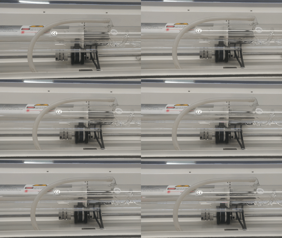
Start the water chiller and verify that the water flows in the right direction in the laser source. It should flow from left to right (if you are standing behind the laser machine). If this is not the case, reverse the hoses on the inlet and outlet. Now keep the water chiller running for a few hours until you see no more air bubbles in the laser source. If after about three hours you still see some air bubbles, you can pinch the hose a little to give a jolt to the water to release them. As soon as the water, without air bubbles, circulates well with the water chiller on, the laser machine can be used again.
## Air bubbles in the laser source
[Section titled “Air bubbles in the laser source”](#air-bubbles-in-the-laser-source)
Air bubbles in the laser source can cause irreparable damage. Air is a very poor heat conductor, especially compared to water. Therefore, if there are too many or too large air bubbles at one place, that area can become hotter than the rest of the laser source. This can cause thermal stress on the glass, slightly distorting it, but enough to cause the laser to not cut as well as it should. There can also be so much heat that the laser source breaks because the glass can no longer handle the stress. That is why it is crucial to check the laser source for air bubbles.
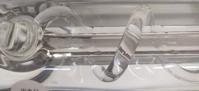
# Problems and solutions
### Co2 Machines
***
[Adjust and replace belts of the X- and Y-axes of the BRM OriginalA BRM Laser has 3 timing belts that need to be checked regularly and tensioned if necessary. There are 2 Y-axis belts and 1 X-axis belt. The Y-axis belts are located to the left and right of the work area. The X-axis belt is located on the bridge, from left to right and starts and ends at the laser head.](/en/problems-and-solutions/co2-machines/brm-original-belts-of-the-x--and-y--axes-adjustment-and-replacement)
[>](/en/problems-and-solutions/co2-machines/brm-original-belts-of-the-x--and-y--axes-adjustment-and-replacement)
[Help, I have a double line in my cutting and engravingWhen you are cutting or engraving, you may see a second line appear making the exact same shape but just slightly off. When cutting, one line is often a bit thinner and still goes into your material. The second line is often a bit wider and only leaves a superficial trace.](/en/problems-and-solutions/co2-machines/help-there-is-a-double-line-in-my-cutting-and-engraving-work)
[>](/en/problems-and-solutions/co2-machines/help-there-is-a-double-line-in-my-cutting-and-engraving-work)
[Machine protected error on the BRM SlimWhen the Machine Protected error appears on the machine's display, you cannot move the axes or continue working with the machine. The error must be resolved before you can continue.](/en/problems-and-solutions/co2-machines/machine-protected-error-on-the-slim)
[>](/en/problems-and-solutions/co2-machines/machine-protected-error-on-the-slim)
[Potential error messages on the machineError messages are never convenient, see here how to resolve which error.](/en/problems-and-solutions/co2-machines/potential-error-messages-on-the-machine)
[>](/en/problems-and-solutions/co2-machines/potential-error-messages-on-the-machine)
[Shapes do not connectYou have loaded in the machine a drawing with for example circles. After the machine finishes cutting, you see that the start and end points of the cutting line do not match.](/en/problems-and-solutions/co2-machines/shapes-do-not-connect)
[>](/en/problems-and-solutions/co2-machines/shapes-do-not-connect)
[The laser head of my BRM Original is no longer perpendicularIf you have had a collision between the laser head and your material, this may have happened with a lot of force. Because of this it is possible that the laser head is no longer completely perpendicular. If the head is not completely perpendicular, it can affect your cutting and engraving results. For example, you will have less power or a shadow line will appear, a second line next to your cutting or engraving line.](/en/problems-and-solutions/co2-machines/the-laser-head-of-my-brm-original-is-not-at-90-angle-any-more)
[>](/en/problems-and-solutions/co2-machines/the-laser-head-of-my-brm-original-is-not-at-90-angle-any-more)
[The laser head of my BRM Pro is not at a 90° angle any moreIf you have had a collision between the laser head and your material, this may have happened with a lot of force. Because of this it is possible that the laser head is no longer completely perpendicular. If the head is not completely perpendicular, it can affect your cutting and engraving results. For example, you will have less power or a shadow line will appear, a second line next to your cutting or engraving line.](/en/problems-and-solutions/co2-machines/the-laser-head-of-my-brm-pro-is-not-perpendicular)
[>](/en/problems-and-solutions/co2-machines/the-laser-head-of-my-brm-pro-is-not-perpendicular)
[The machine has problems with referencingWhen you turn on the machine, the machine should be referenced. The X and Y axes then go to the upper right corner and the table also goes to the 0 position. The axes then move toward a sensor. When the axes are at the sensor, the axes know where their zero point is. From this zero point, the machine knows where the limit is and where the axis must stop to avoid collisions with the body of the machine.](/en/problems-and-solutions/co2-machines/the-machine-has-problems-with-referencing)
[>](/en/problems-and-solutions/co2-machines/the-machine-has-problems-with-referencing)
[The Red Pointer of my BRM Original is no longer visibleIf you have a BRM Original then chances are you have a Red Pointer. The Red Pointer allows you to see a guide line which can be useful when you want an indication of approximately where you are going to cut or engrave.](/en/problems-and-solutions/co2-machines/the-red-pointer-of-my-brm-original-is-no-longer-visible)
[>](/en/problems-and-solutions/co2-machines/the-red-pointer-of-my-brm-original-is-no-longer-visible)
[The Y-axis of my BRM Budget does not workThe Y-axis of my BRM Budget does not work](/en/problems-and-solutions/co2-machines/the-y-axis-of-my-brm-budget-does-not-work)
[>](/en/problems-and-solutions/co2-machines/the-y-axis-of-my-brm-budget-does-not-work)
[The Y axis of my BRM Original is not workingIf the Y axis of your BRM Original is not working there could be a couple of things going on. When you start the machine then press the reset button on the switch panel. The axes now drive to the right rear of the machine. After the machine does the reset the red alarm light goes out.](/en/problems-and-solutions/co2-machines/the-y-axis-of-my-brm-original-does-not-work)
[>](/en/problems-and-solutions/co2-machines/the-y-axis-of-my-brm-original-does-not-work)
[The Y axis of my BRM Pro is not workingThe Y axis of my BRM Pro is not working.](/en/problems-and-solutions/co2-machines/the-y-axis-of-my-brm-pro-does-not-work)
[>](/en/problems-and-solutions/co2-machines/the-y-axis-of-my-brm-pro-does-not-work)
[The Y axis of my BRM Slim is not workingThe Y axis of my BRM Slim is not working.](/en/problems-and-solutions/co2-machines/the-y-axis-of-my-brm-slim-does-not-work)
[>](/en/problems-and-solutions/co2-machines/the-y-axis-of-my-brm-slim-does-not-work)
[The Z axis of the BRM Original is not workingIf the Z axis of the BRM Original no longer works that there are a number of things you could check yourself.](/en/problems-and-solutions/co2-machines/the-z-axis-of-my-brm-original-does-not-work)
[>](/en/problems-and-solutions/co2-machines/the-z-axis-of-my-brm-original-does-not-work)
[There are vibrations in the engraving linesOften vibrations in an engraving occur in the first and last part of the complete engraving. Vibration may also be present at the beginning of the engraving line.](/en/problems-and-solutions/co2-machines/there-are-vibrations-in-the-engraving-lines)
[>](/en/problems-and-solutions/co2-machines/there-are-vibrations-in-the-engraving-lines)
[I don't have a laser beamIf you are not getting a laser beam on your material, there could be a number of things going on.](/en/problems-and-solutions/co2-machines/there-is-no-laser-beam)
[>](/en/problems-and-solutions/co2-machines/there-is-no-laser-beam)
[There is an offset in the cutting or engraving lineWhen you are cutting something the line may suddenly jump a little bit. Suppose you are cutting a square and suddenly the horizontal line (X-axis) jumps a little bit. Then there is a problem in the Y-axis. The same is true in reverse, if there is a stagger in the vertical line (Y-axis) then there is a problem on the X-axis.](/en/problems-and-solutions/co2-machines/theres-an-offset-in-the-cutting-or-engraving-line)
[>](/en/problems-and-solutions/co2-machines/theres-an-offset-in-the-cutting-or-engraving-line)
### Metallaser
***
[How to connect oxygen to the BRM 90130-X or the BRM Budget 90130-XA 150 W laser source by itself does not have enough power to cut through metals. By adding oxygen you feed the fire allowing you to put enough power into the material and cut.](/en/problems-and-solutions/metal-laser/how-do-i-connect-oxygen-to-the-brm90130-x-or-the-brm-budget90130-x)
[>](/en/problems-and-solutions/metal-laser/how-do-i-connect-oxygen-to-the-brm90130-x-or-the-brm-budget90130-x)
[What metals can I cut with my BRM 90130-X or BRM Budget 90130-X?I have a the BRM90130-X or a budget90130-X and I would like to know if I can cut certain metals. Please note that the machine must be suitable for cutting metal! If the machine is not suitable for cutting metal and you try to do it anyway, the machine may break down.](/en/problems-and-solutions/metal-laser/what-metals-can-i-cut-with-my-brm90130-x-or-brm-budget90130-x)
[>](/en/problems-and-solutions/metal-laser/what-metals-can-i-cut-with-my-brm90130-x-or-brm-budget90130-x)
# Adjust and replace belts of the X- and Y-axes of the BRM Original
> A BRM Laser has 3 timing belts that need to be checked regularly and tensioned if necessary. There are 2 Y-axis belts and 1 X-axis belt. The Y-axis belts are located to the left and right of the work area. The X-axis belt is located on the bridge, from left to right and starts and ends at the laser head.
A BRM Laser has three timing belts that require regular checking and tensioning. There are 2 Y-axis belts and 1 X-axis belt. The Y-axis belts are located to the left and right of the work area. The X-axis belt is on the bridge, from left to right, starting and ending at the laser head.
Check the timing belts regularly to make sure they still have the correct tension. If a belt is adjusted too loosely or too tightly, you will notice your machine does not cut or engrave as well as it should. Improper tension can also cause the belt to malfunction.
## How do I know if the timing belt has the correct tension?
[Section titled “How do I know if the timing belt has the correct tension?”](#how-do-i-know-if-the-timing-belt-has-the-correct-tension)
Position the bridge at the front or rear of the machine. Move the laser head to the left or right. Twist the belt at a 90° angle. Can the belt rotate more than 90°? Then the tension is too low. The tension is too high when it can rotate less than 90°. Repeat this procedure for all belts.
## How do I adjust the tension of the belt?
[Section titled “How do I adjust the tension of the belt?”](#how-do-i-adjust-the-tension-of-the-belt)
The timing belts are fastened with clamps. There are 2 Allen bolts recessed in the clamp. These can be used to tighten or loosen the belt.
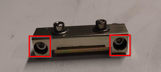
To adjust the Y-axis belt(s), use the small clamps on the front side. To adjust the X-axis belt, use the small clamp on the left of the laser head.
By turning the Allen bolts in, you tighten the belt; turning them out loosens the belt. Make sure to turn both bolts in or out by the same amount. That ensures tension on the belt remains even. If you notice that the belt is twisting, you will need to turn the Allen bolts in and out until the belt itself is straight. That will prevent it from tearing.
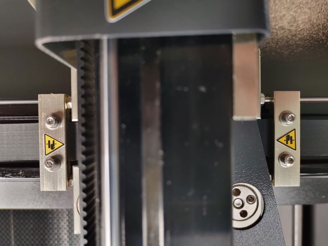
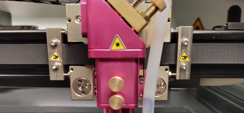
Turn in or out a little and check the tension again. Continue this process until the belt has the correct tension. The belt has a clamp at both ends. Adjust the belt with one of the clamps, not with both of them. If you need to use the rear clamp to adjust the Y-axis, use the rear clamp for the other Y-axis belt also. If you adjust one side in front and the other in back, the bridge may become slightly misaligned. That will result in a deviation in the dimensions of your work.
Unable to tighten anymore, but this seems necessary? Unscrew the Allen bolts of one clamp completely. Loosen the bolts on top of the clamp. That allows you to open the clamp. Move the belt 1 tooth further into the clamp and tighten the clamp again. Tighten the Allen bolts again to adjust the belt.
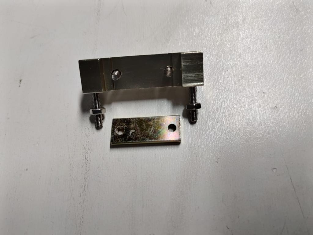
When you need an extra tooth next time, it is time to replace the belt(s). The belt has lost its proper tension and you can start to see effects in your work.
## My timing belt is damaged or has lost tension, how do I replace a belt?
[Section titled “My timing belt is damaged or has lost tension, how do I replace a belt?”](#my-timing-belt-is-damaged-or-has-lost-tension-how-do-i-replace-a-belt)
If, for example, your belt is missing a tooth, has lost its elasticity or is defective in some other way, you will have to replace it. When replacing a Y-axis belt, it is advisable to replace the other Y-axis belt as well.
Loosen both clamps with the 2 Allen bolts. Leave the belt in the clamps. Undo one of the clamps. Ideally, remove the belt from the clamp on the front (Y-axis) or left (X-axis). Leave the other clamp on the belt.
If possible, use tape to stick the new belt to the end of the old one. Try to do this as well as possible but do not build up the tape too much. Then you can pull on the old belt. Keep the belt as flat as possible. By doing this, you pull the new belt along, making it easier to position it in the right place. Make sure to do this carefully to ensure the belts stay together.
Once the new belt is visible and can be easily reached, you can separate the belts. Remove the clamp from the old belt and attach it to the new one. Attach the clamp to the side of the belt you just pulled through the machine.
If you replace both belts on the Y-axis, you first replace one, then the other. Once you have done this, proceed to the next steps.
**Y-axis**. Place the belt flat on the bridge. Keep the clamp side against the panel where the clamp is to be attached. At the front, place the belt against the small panel where the clamp will be mounted. Pull the belt a little tighter by hand. Then hold the tooth that just touches the panel. Cut the belt here.
**X-axis**. Place the belt flat on the bridge. Keep the clamp side against the panel on the left side of the laser head in which the clamp is mounted. On the right side of the head, place the belt against the head. Tighten the belt a little by hand. Then hold the tooth that just touches the panel. Cut the belt here.
Once the belt is at its correct length, take hold of the cut end of the belt. Place the second clamp on the belt at the third tooth from the beginning of the belt. The belt will therefore stick out a little through the clamp. Fasten the clamp.

Now mount the side of the belt where you first mounted the clamp. For the Y-axis this is at the back. For the X-axis, this is on the left side of the head. Leave about a centimeter of space between the clamp and the mounting panel. Make sure that the clamp is not set against the mounting panel! For an Open Bed laser machine, leave about 1.5 centimeters of space.
When the clamp is properly mounted, move the bridge all the way back (Y-axis) or the head all the way to the left ( X-axis). Move the clamp that is not yet fixed to the attachment point. The belt will now be tensioned and you can tighten the clamp with the two Allen bolts. Because you have moved the bridge backwards and/or the laser head to the left, they give counter pressure so that you can easily fasten the clamp without pushing away the bridge / head.
Rotate the Allen bolts half a turn each, until you obtain the correct tension.
If you have trouble getting it done or would like a technician to do it, please send us a [ticket](/en/contact) so we can help you out
# Help, I have a double line in my cutting and engraving
> When you are cutting or engraving, you may see a second line appear making the exact same shape but just slightly off. When cutting, one line is often a bit thinner and still goes into your material. The second line is often a bit wider and only leaves a superficial trace.
When you are cutting or engraving, you may notice a second line appearing with the same shape but slightly off. When cutting, one line is often thinner and still goes into the material. The second line is usually wider and leaves a superficial mark only.
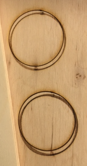
## What causes this ‘shadow line’?
[Section titled “What causes this ‘shadow line’?”](#what-causes-this-shadow-line)
This shadow line occurs because the laser beam in the nozzle, the tip at the bottom of the lens shaft, hits the side of the hole. Normally, the laser beam passes through the center of the hole in the nozzle. If the beam does not pass through the center, it collides with the material of the nozzle. This means you do not have a proper laser beam on your product and there can therefore be a second line.
You can check this by sticking a piece of masking tape on the bottom of the nozzle and shooting a pulse. Then unscrew the nozzle from the lens shaft and look through the nozzle hole from the inside. Please be careful, the nozzle may have become hot! If all goes well then you will see that the hole in the masking tape is nicely centered inside the hole in the nozzle. When there is a deviation then you will see that the hole in the masking tape is not sitting nicely in the center of the hole in the nozzle. It also often happens that the hole in the tape is not round but has become oval.
## How do I correct the ‘shadow line’?
[Section titled “How do I correct the ‘shadow line’?”](#how-do-i-correct-the-shadow-line)
Establish whether you have had a collision with your material. If there has been a hard collision then the laser head may no longer be perpendicular to the table. A small deviation can be enough to cause a ‘shadow line’.
If you notice that the laser head is not perpendicular to the table, you will have to adjust the alignment of the laser head.
Click [here](/en/problems-and-solutions/co2-machines/the-laser-head-of-my-brm-pro-is-not-perpendicular) to read more about how to align the laser head of the [BRM Pro](https://www.brmlasers.com/product/pro-1300?utm-source=support-site).
Click [here](/en/problems-and-solutions/co2-machines/the-laser-head-of-my-brm-original-is-not-at-90-angle-any-more) to read more about how to align the laser head of the [BRM Original](https://www.brmlasers.com/product/pro-1300?utm-source=support-site).
If the laser head is perpendicular to the table or you have adjusted the perpendicularity of the laser head, you need to check the mirror alignment completely. A shadow line can also arise from mirror alignment that is slightly off.
If you can’t solve the problem, we will be happy to help. Just send us a [ticket](/en/contact) with some pictures of your result and we will look into how we can help you best.
# Machine protected error on the BRM Slim
> When the Machine Protected error appears on the machine's display, you cannot move the axes or continue working with the machine. The error must be resolved before you can continue.
When the Machine Protected error appears on the machine display, you cannot move the axes or continue working with the machine. The error needs to be resolved before you can continue.
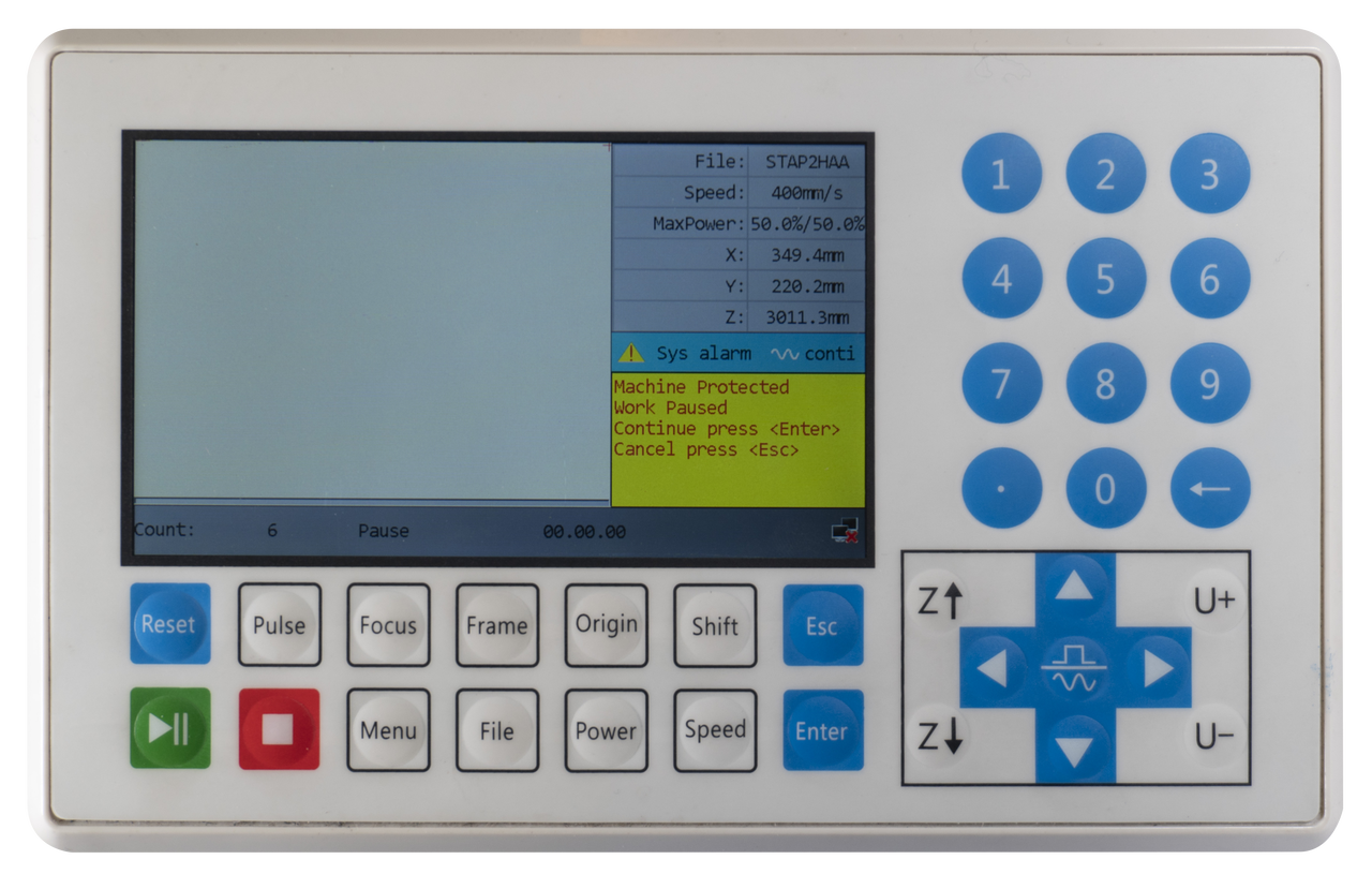
## What causes the Machine Protected error?
[Section titled “What causes the Machine Protected error?”](#what-causes-the-machine-protected-error)
The Machine Protected error occurs when one of the door sensors has no connection. Whenever there is no connection, dangerous situations may arise when continuing work. There is a clamping hazard, a danger of being pulled and a risk of radiation. To prevent that, the axes and the laser beam switch off when a sensor is no longer connected.
The Machine Protected error also occurs when the emergency stop is activated. If you want to start a program or move the axes while the emergency stop is active, the Machine Protected error is indicated.
## How do I solve the Machine Protected error?
[Section titled “How do I solve the Machine Protected error?”](#how-do-i-solve-the-machine-protected-error)
When the Machine Protected error occurs, a blue light in the Reset button also lights up. This blue light allows you to determine which sensor is not connecting.
The light will be on for some time and will then quickly switch off and back on again for some time. When the emergency stop button is pressed, the light is on continuously.
When the light is on for **1** second, the problem is with the main door. This sensor fails to connect.
When the light is on for **3** seconds, the problem is at the laser source door and/or at the top left cover. One of these sensors fails to connect.
When the light is on for **6** seconds, the problem is with the front door and/or the top right cover. One of these sensors fails to connect.
When the light is on **continuously**, the emergency stop button is activated.
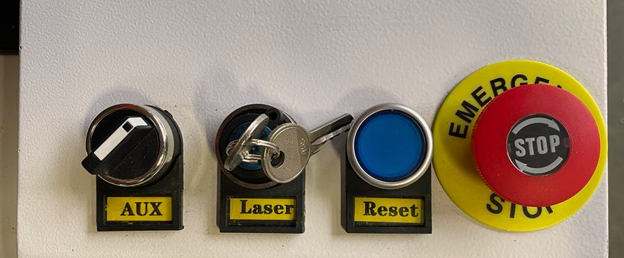
Once you know which sensor is causing the error, you can check whether the door / cover is open. If it is, please close it. The light should go out now after which you can press **\[Esc]**. You can then continue your work. If the emergency stop is activated and you switch it off by rotating it clockwise, you need to press the Reset button as well. The machine will reset itself and the blue light will go out. You can start to use the machine again.
Are all the doors closed but do you still get the error message? Check which sensor might be the cause by observing the blue light and opening the corresponding door / cover. When opened, you can close the door again. That may solve the error.
## I have completed all the steps, but the Machine Protected message does not disappear
[Section titled “I have completed all the steps, but the Machine Protected message does not disappear”](#i-have-completed-all-the-steps-but-the-machine-protected-message-does-not-disappear)
Make sure you have pressed **\[Esc]** on the display. If you click the message away and you want to do something, like starting, and the message reappears, there is probably something else wrong with the sensor.
A mechanic will have to come and examine everything and replace what is necessary. Please submit a [ticket](/en/contact) for this service.
# Potential error messages on the machine
> Error messages are never convenient, see here how to resolve which error.
## Machine protected
[Section titled “Machine protected”](#machine-protected)

This error occurs if one of the doors of the laser machine is not closed properly. This applies to all doors of the areas the laser beam can reach. This error can also occur when the doors are closed but that signal is not registered.
If the doors are closed properly, you can open the doors one by one and close them again. If one of the sensors does not register the closed door properly, this may cause it to re-register and work properly. If all the doors are closed and opening and closing them all again does not work, check if the emergency stop is active, this can also cause the error. If this is not the case, it may be that one of the sensors is no longer functioning. In this case, an on-site technician is required.
## Hard Limit Prot
[Section titled “Hard Limit Prot”](#hard-limit-prot)
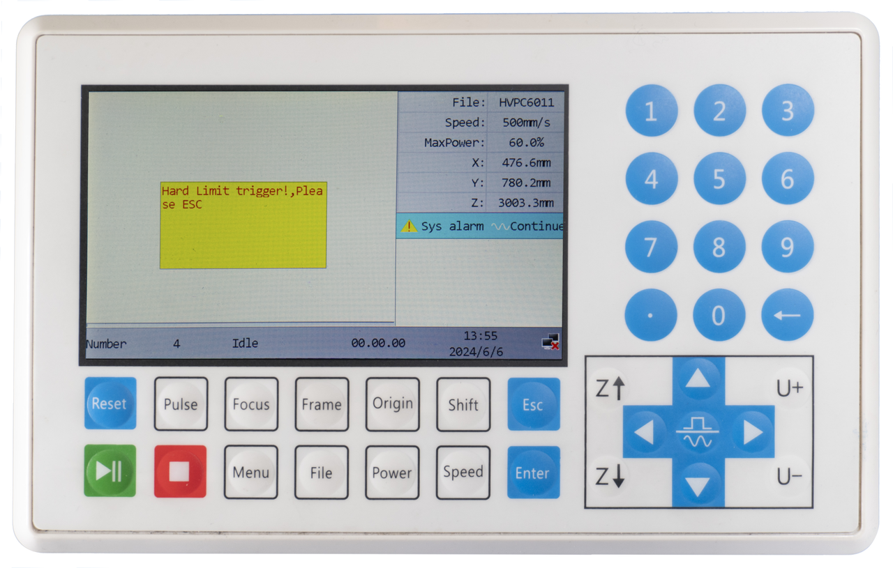
This error appears when the Y, X, or Z sensors are reached. It may occur, for example, when you have not referenced the axes. The Hard Limit Prot can occur when the X- or Y-axis detects the sensor. The axis can then not move any further and an error occurs.
You can avoid the Hard Limit Prot by always referencing the axes when you switch the machine on. The Hard Limit Prot on the Z-axis can be prevented by making sure the laser head is not set too low when working with the autofocus. You also need to slightly lower the Z-axis from the top position to make sure there is enough space to get the correct height between material and autofocus sensor. In the diagnostic screen **\[Menu => Function+ => Diagnoses+]** you can check the Hard Limit Prot so you can see to which axis it applies.
## X Slop over
[Section titled “X Slop over”](#x-slop-over)
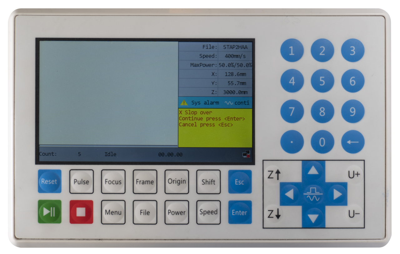
This error occurs when the machine has to move out of the range of the X-axis to cut / engrave the work. This can be the case, for example, when you want to cut or engrave the product in a corner and you have set the origin of the work outside the work area.
Below is a screenshot to illustrate this. If the machine notices that part of your work is outside the work area, it cannot make the move.
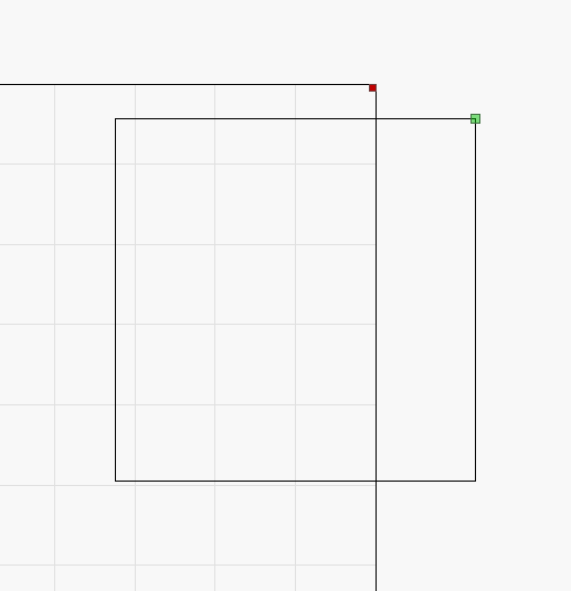
When you work with the Origin button on the machine, you need to move the axes to a position further from the edge. Then click Origin again to set the new position as the origin.
When using the Absolute Coordinate from the software, you need to move the drawing in the software so it is further from the edge.
You also have to check the software to see where the origin of your drawing is located. If you intend to work in the top right corner and have pressed the Origin button to set the origin here, it may be that the origin of the drawing is in the top left corner. As a result, the machine calculates from the top left corner and the laser head must move to the right. This is impossible, however, because the machine’s work area stops here. If you set the origin of the drawing to the top right, you can start cutting at this spot because the laser head will now move to the left and there is enough space here.
The green dot in the drawing indicates the origin of the drawing. See the examples below.


To change the origin of the drawing, you can choose from several points:
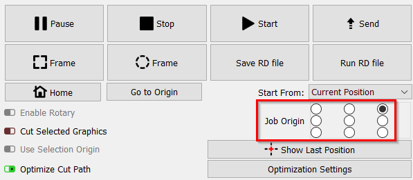
This error can also occur when you are going to do an engraving / marking that is too close to the edge of the work area. During engraving / marking, the laser head needs space to accelerate and decelerate. Your work will then be within the working area, but there will be insufficient space for the machine to reach speed or slow down. The error will also occur in this case.
Below is an example of the error occurring during engraving.

If this is the case, you will need to move your work more to the center of your workspace. When you select Continue and press **\[Enter]**, the machine may start doing what it is supposed to do. However, the error will return as soon as it receives the signal that the laser head should move outside the work area. This may occur, for example, halfway through your engraving and then you will have to stop the program. Press **\[Esc]** to stop the program. You can select another place to start working and then press **\[Start]** again. If you choose Cancel and press **\[Esc]**, you will stop and can choose a new position to work.
## Y Slop over
[Section titled “Y Slop over”](#y-slop-over)
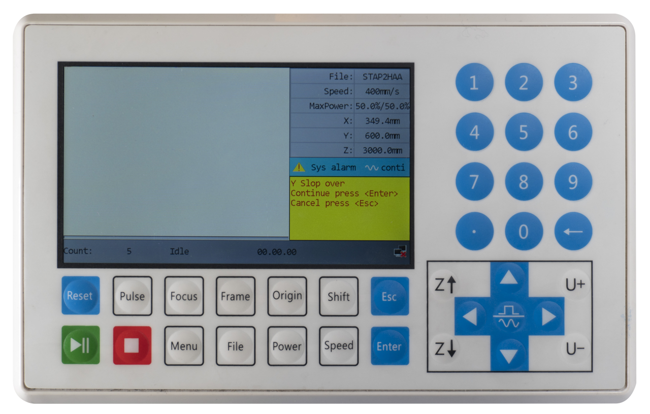
This error occurs when the machine has to move out of the range of the Y-axis to cut / engrave the work. This can be the case, for example, when you want to cut or engrave the product in a corner and you have set the origin of the work outside the work area.
Below is a screenshot to illustrate this. If the machine notices that part of your work is outside the work area, it cannot make the move.

When you work with the Origin button on the machine, you need to move the axes to a position further from the edge. Then click **\[Origin]** again to set the new position as the origin.
When using the Absolute Coordinate from the software, you need to move the drawing in the software so it is further from the edge.
You also have to check the software to see where the origin of your drawing is located. If you intend to work in the top right corner and have pressed the Origin button to set the origin here, it may be that the origin of the drawing is in the bottom right corner. As a result, the machine calculates from the bottom right corner and the laser head must move to upwards. This is impossible, however, because the machine’s work area stops here. If you set the origin of the drawing to the top right, you can start cutting at this spot because the laser head will now move to the bottom and there is enough space here.
The green dot in the drawing indicates the origin of the drawing. See the examples below.
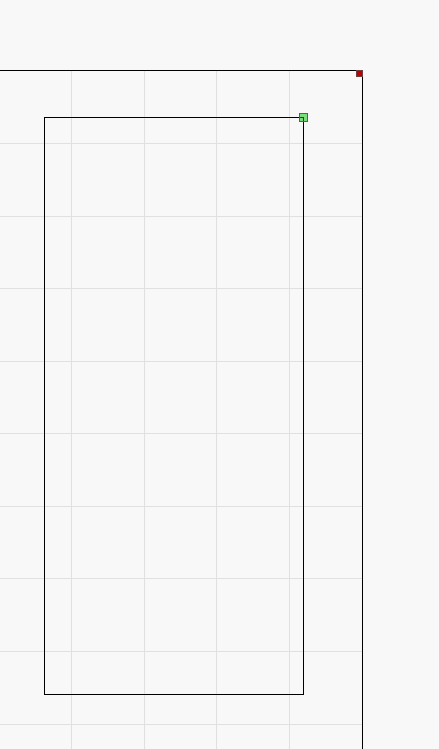 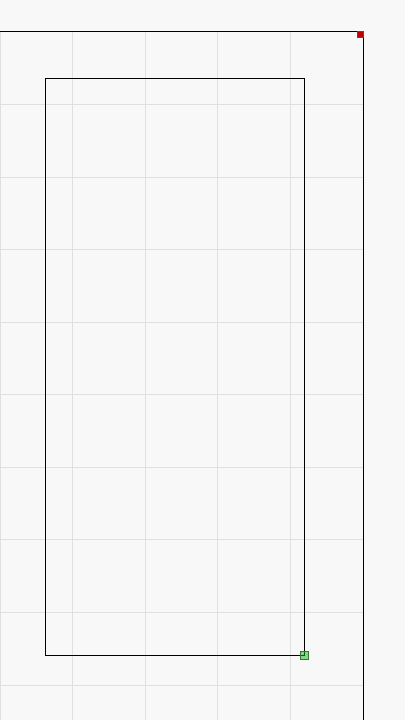
To change the origin of the drawing, you can choose from several points:

This error can also occur when you are going to do an engraving / marking that is too close to the edge of the work area. During engraving / marking, the laser head needs space to accelerate and decelerate. Your work will then be within the working area, but there will be insufficient space for the machine to reach speed or slow down.
Below is an example of the error occurring during engraving.

If this is the case, you will need to move your work more to the center of your workspace.
If the error occurs while working with the rotation axis it will help to move the rotation, using the U+ and U- keys. Basically, the rotation can rotate infinitely. Instead, the rotation is given the dimensions of your workspace. If your workspace on the Y-axis is 900 mm, then the rotation workspace will also be 900 mm. Using the rotation, it is also possible that you are getting too close to the edges of your workspace. If you get the Y Slop over error, do a few rotations by using the U+ and U- buttons. Press the Origin button on the display of the machine.
When you select Continue and press **\[Enter]**, the machine may start doing what it is supposed to do. However, the error will return as soon as it receives the signal that the laser head should move outside the work area. This may occur, for example, halfway through your engraving and then you will have to stop the program. Press **\[Esc]** to stop the program. You can select another place to start working and then press **\[Start]** again. If you choose Cancel and press **\[Esc]**, you will stop and can choose a new position to work.
## Frame slop
[Section titled “Frame slop”](#frame-slop)
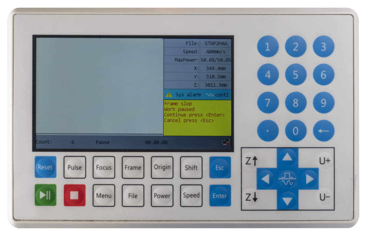
This error occurs when you are framing and your work is outside the work area.
If you are sure that your work is located in the middle of the working area, you may have a guideline or frame in the software you do not want to cut. However, this guideline will be included during the framing process.
It may also be the case that you have not pressed the **\[Origin]** button yet. The machine will then pick the last Origin you entered. This origin might be close to the side of the machine so your work does not fit into the work area causing the error.
When using the Absolute Coordinate from the software, you need to move the drawing in the software so it is further from the edge.
You also have to check the software to see where the origin of your drawing is located. If you intend to work in the top right corner and have pressed origin here, it may be that the origin of the drawing is in the bottom right corner. As a result, the machine calculates from the bottom right corner and the laser head must move upwards. This is impossible, however, because the machine’s work area stops here. If you set the origin of the drawing to the top right, you can start cutting at this spot because the laser head will now move downwards and there is enough space here. The same goes for the other axis. If you want to work at the top right and you have set the origin at the top left, you will also get the error.
The green dot in the drawing indicates the origin of the drawing. See the examples below.


To change the origin of the drawing, you can choose from several points:

For example, if you have a guide frame that you don’t want to cut but the object you do want to cut is small and in the center of the workspace, you can press **\[Enter]** to continue. The framing will continue, however, a piece will be cut off and the framing will no longer be accurate. When you then press the **\[Start]** button on the display of the laser machine, your product will be cut if it is small enough and far enough from the edges of the work area.
When you click **\[Esc]** to cancel, the framing stops. You can check whether you are trying to work too close to the edges of the work area and work a bit further away from them. You can also check whether there is a guide frame or similar in the drawing that is causing the error. You can press the Origin button again to make sure that you are actually working in the indicated place.
## Water prot 1
[Section titled “Water prot 1”](#water-prot-1)
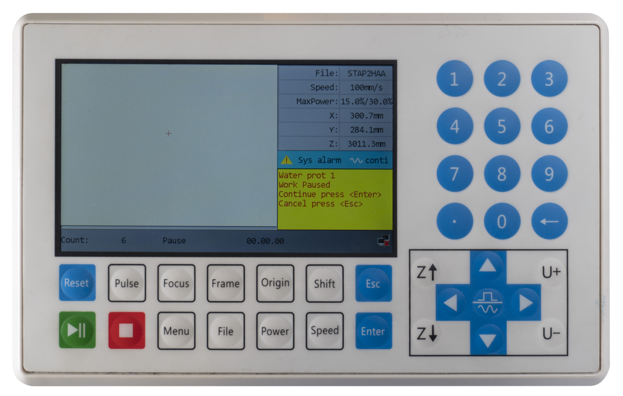
This error indicates that the signal from the water chiller is not received. If this error is present, you cannot cut or engrave / mark. The water in the laser source must be continuously pumped around to prevent damage.
If the Water prot 1 is going on then the water chiller may not be on. Check to see that the Auxiliary switch is properly set. On the [BRM Pro](https://www.brmlasers.com/product/pro-1300?utm-source=support-site), the switch is on the right side of the machine, on the switch panel. On the [BRM Slim](https://www.brmlasers.com/product/slim-1300?utm-source=support-site), the switch is above the display on the machine. If it is switched on, you can then check whether the water chiller itself is switched on.
When the water chiller is on, the alarm cable at the back of it may not be connected properly or may have come out. If the alarm cable is not connected properly, remove it from the water chiller and plug it in again.
If everything is connected correctly, the water chiller might be indicating an alarm. You can see this on the display of the water chiller. It may show an error code. The red light below the display may also be lit and the alarm signal may sound.
Depending on the type of malfunction of the water chiller, a BRM technician may be required. If everything is switched on and the water chiller does not raise an alarm but the error persists, a BRM technician is required.
## Machine Protected
[Section titled “Machine Protected”](#machine-protected-1)
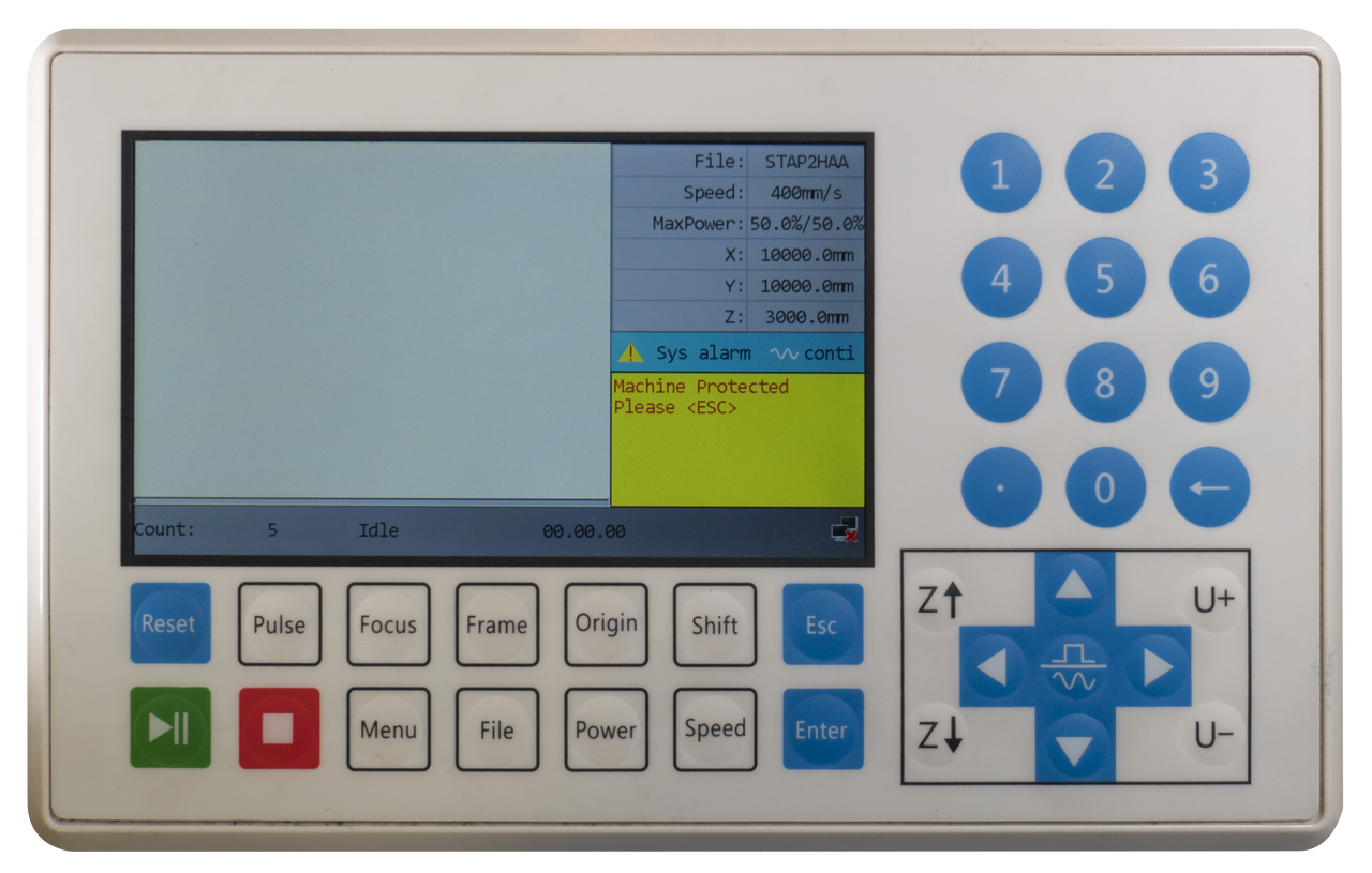
This error occurs if one of the doors is not closed properly or when the emergency stop button is activated. This applies to all doors of the areas the laser beam can reach. This error can also occur when the doors are closed but that signal is not registered.
If the doors are closed properly, you can open the doors one by one and close them again. If the sensor does not register the closed doors properly, this may cause it to re-register and work properly.
If you have checked the doors and everything seems to be correct then you can press **\[Enter]** to continue. The machine has gone into pause mode so when you press **\[Enter]** you continue where you left off.
Pressing **\[Esc]** stops your program. The laser head goes back to where you started cutting / engraving. If you want to continue with the same program you will have to start it again.
If all the doors are closed and opening and closing them all again does not work, it may be that one of the sensors is no longer functioning. In this case, an on-site technician is required. You can always send us a [ticket](/en/contact) in case you require help.
# Shapes do not connect
> You have loaded in the machine a drawing with for example circles. After the machine finishes cutting, you see that the start and end points of the cutting line do not match.
You have uploaded a drawing with, for example, circles into the machine. After the machine has finished cutting, you notice that the start and end points of the cutting line do not meet.
## Check the mirrors and the lens
[Section titled “Check the mirrors and the lens”](#check-the-mirrors-and-the-lens)
First, you can check if one of the mirrors is loose. It is also possible that the lens is loose or misaligned. If this is the case, you can carefully tighten the mirror or lens. Then run a test to see if this solves the problem. You might have to check the complete mirror alignment after tightening the mirror or lens.
## Is the belt tension correct?
[Section titled “Is the belt tension correct?”](#is-the-belt-tension-correct)
This problem can also be caused by play on the timing belts. If you are going from right to left you are traveling a different path than from left to right. Check whether the tension of the belts is still correct. The belts should not be too loose, but certainly not too tight. The belts of the Y-axis should have about the same tension.
Please read more about adjusting the timing belts of the BRM Original [here.](/en/problems-and-solutions/co2-machines/brm-original-belts-of-the-x--and-y--axes-adjustment-and-replacement)
## Are the timing belt pulleys secured?
[Section titled “Are the timing belt pulleys secured?”](#are-the-timing-belt-pulleys-secured)
Check whether the timing belt pulleys are securely fastened. A timing belt pulley sits over an axis. The axis is round but has a small flat area. In the timing belt pulley, there is a locking bolt. If the locking bolt has loosened slightly, the timing belt pulley can rotate further than it should and there will be play. If you notice that the timing belt pulley is very loose, you need to tighten the locking bolt. Rotate the timing belt pulley until you see the locking bolt and the timing belt is no longer on top of it. Tighten the locking bolt with an Allen key. Also, check whether the timing belt is intact. There is a possibility it is damaged by the locking bolt. If the timing belt is damaged, it will have to be replaced.

If you do not find an abnormality or if you are not sure whether something is abnormal or not, please submit a [ticket](/en/contact) so we can help you out.
# The laser head of my BRM Original is no longer perpendicular
> If you have had a collision between the laser head and your material, this may have happened with a lot of force. Because of this it is possible that the laser head is no longer completely perpendicular. If the head is not completely perpendicular, it can affect your cutting and engraving results. For example, you will have less power or a shadow line will appear, a second line next to your cutting or engraving line.
## How come your laser head is not at a 90° angle anymore?
[Section titled “How come your laser head is not at a 90° angle anymore?”](#how-come-your-laser-head-is-not-at-a-90-angle-anymore)
If you have had a collision between the laser head and your material, this may have happened with a lot of force. As a result, the laser head may not be positioned squarely. If the laser head is not exactly at a 90° angle, this can affect your cutting and engraving results. For example, you may have less power or a shadow line may appear next to the cutting or engraving line.
## Checking that your laser head is at a 90° angle
[Section titled “Checking that your laser head is at a 90° angle”](#checking-that-your-laser-head-is-at-a-90-angle)
The first thing to do is to check whether the head is really not at a 90° angle. Position the laser head approximately in the middle of your work area. Place something in your work area, under the laser head, that is completely even and has the same height everywhere. For example, consider a piece of acrylic.
Remove the nozzle mount with nozzle from the lens shaft. The nozzle mount is the ring that holds the air connection.
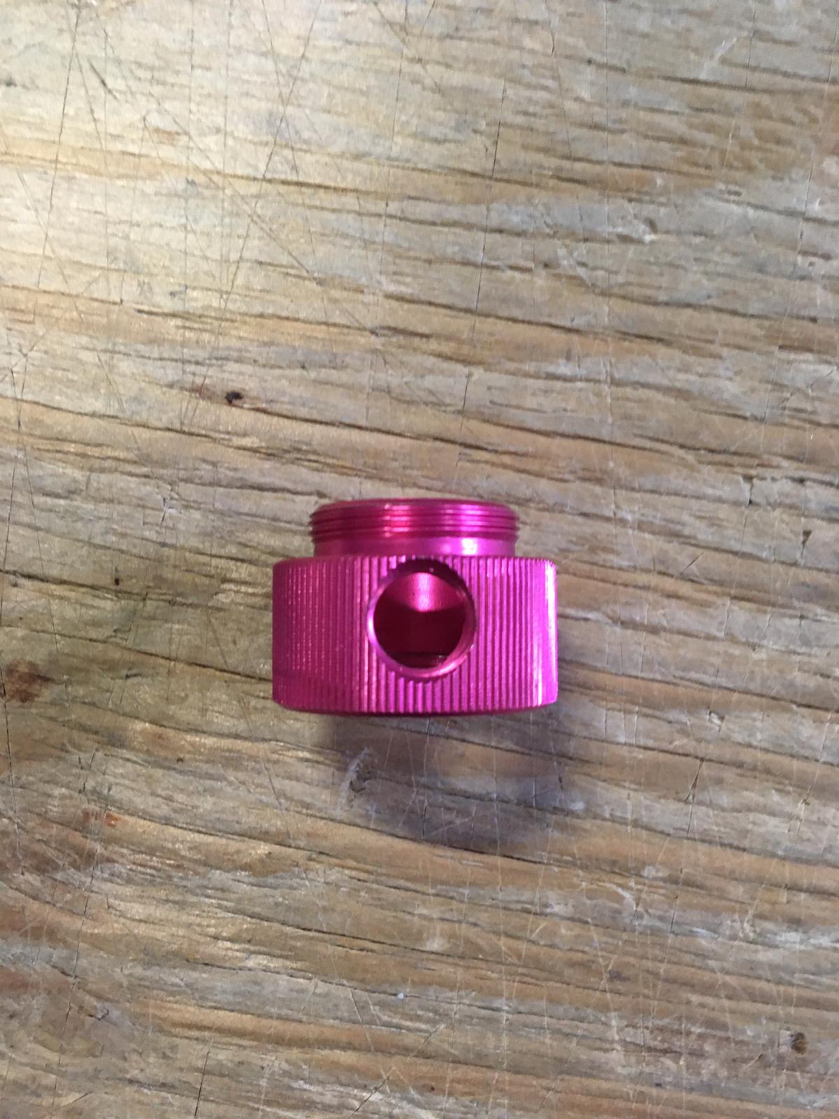
Then take a right-angle square tool and place it on the acrylic against the laser head. If the right-angle square tool lines up nicely, the head is at 90 degrees. Should there be any space between the laser head and the right-angle square tool, you need to adjust the laser head.
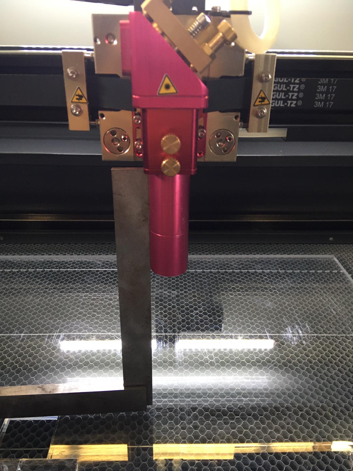
When adjusting the laser head, first remove the lens shaft. Put the lens shaft somewhere safe so nothing can happen to it. When you look at the laser head, you will see two slots with small Allen bolts on the left side of it. On the right side of the laser head, there is one slot with an Allen bolt.
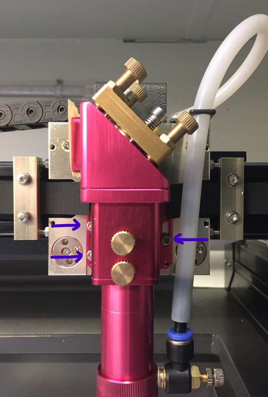
Loosen 2 of the Allen bolts a little, while still holding the laser head. Loosen the third one slightly but not more than that. You should be able to move the laser head, but it should not drop. By leaving one Allen bolt reasonably tight, you can still adjust but the laser head will remain at the correct height.
While adjusting the laser head, keep looking at the right-angle square tool to ensure the laser head will be at a 90° angle. As soon as it is at a 90° angle, you can tighten all Allen bolts again. After you have tightened everything, check whether the laser head is still at a 90° angle by using the right-angle square tool.
Once you have checked that the laser head is indeed at a 90° angle again, you can replace the lens shaft. Replace the nozzle mount with the nozzle and air coupling and reconnect the air hose to the air coupling.
Because you have made adjustments to the laser head, the last thing you need to do is check the mirror alignment and adjust it where necessary to ensure the laser beam hits your material correctly again.
If you cannot work this out, please send us a [ticket](/en/contact) and we will help you.
# The laser head of my BRM Pro is not at a 90° angle any more
> If you have had a collision between the laser head and your material, this may have happened with a lot of force. Because of this it is possible that the laser head is no longer completely perpendicular. If the head is not completely perpendicular, it can affect your cutting and engraving results. For example, you will have less power or a shadow line will appear, a second line next to your cutting or engraving line.
The [BRM Pro](https://www.brmlasers.com/product/pro-1300?utm-source=support-site) laser head perpendicular adjustment guide.
## How come your laser head is not at a 90° angle anymore?
[Section titled “How come your laser head is not at a 90° angle anymore?”](#how-come-your-laser-head-is-not-at-a-90-angle-anymore)
If you’ve had a collision between the laser head and your material, it may have been with a lot of force. As a result, the laser head may no longer be completely perpendicular. If the laser head is not completely perpendicular to the table, it can affect your cutting and engraving results. For example, you will have less power or a shadow line, a second line next to your cutting or engraving line, will appear.
## Checking that your laser head is at a 90° angle
[Section titled “Checking that your laser head is at a 90° angle”](#checking-that-your-laser-head-is-at-a-90-angle)
First, you are going to check if the laser head is not perpendicular to the table. Place the laser head approximately in the middle of your work area. Place something in your work area, under the laser head, that is completely flat and has the same height everywhere. For example, a piece of acrylic. Take a right-angle square tool and place it on the acrylic against the laser head. Ensure you check it does not touch the autofocus mount because that will give a distorted result. If it is the case that the right-angle square tool does touch it, it is best to remove the lens shaft from the laser head.
The first thing you do is disconnect the autofocus sensor. At the top of the sensor is a black plug with a silver ring. Twist the ring and then you can pull up the plug. You also remove the air hose from the air connector. There is a blue ring on the air connector. Press this and while pressing the blue ring, pull the air hose out of the connector. Unscrew the brass-colored bolt on the front of the laser head and make sure you are holding the lens shaft, so it does not fall.
Once the lens shaft is out of the laser head, you can put the right-angle square tool back against the laser head. If it fits nicely, the head is perpendicular. If there is some space between the head and the right-angle square tool, you will need to adjust the laser head.
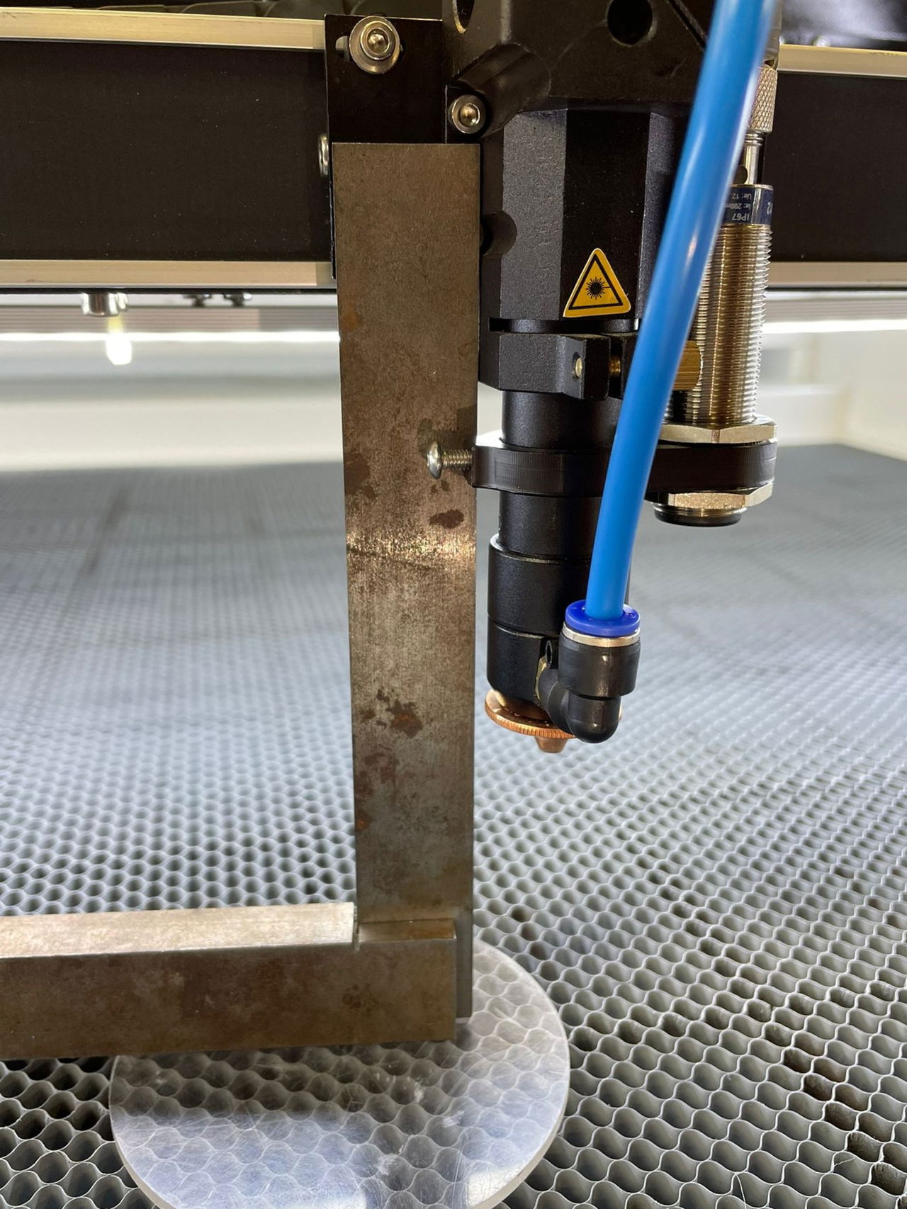
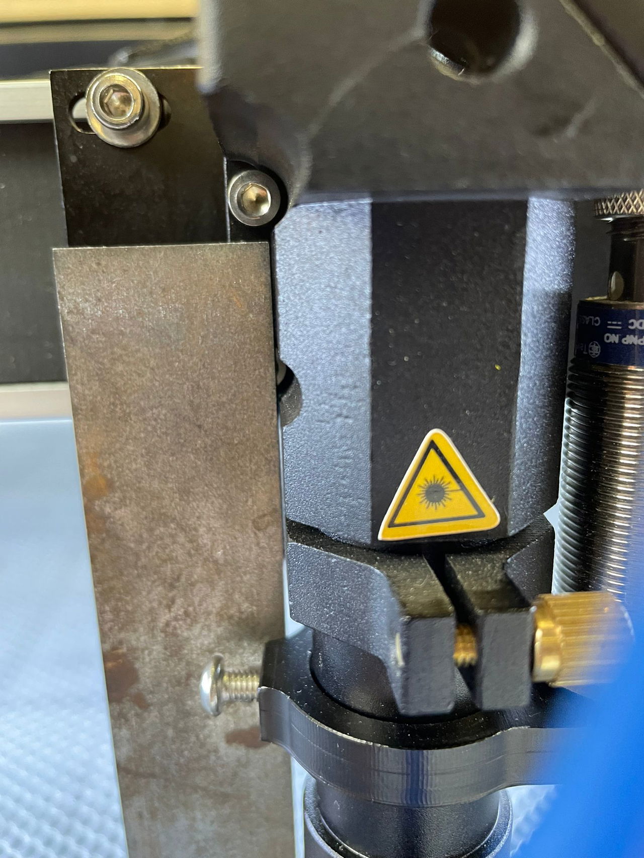
On the left side of the laser head are 2 Allen bolts. With these, you can adjust the laser head. You will need to loosen both Allen bolts a little. Don’t unscrew them entirely, a few twists are enough. If these Allen bolts are a little loose, you have some leeway on the laser head so you can adjust it squarely. That is done by pushing against the laser head.
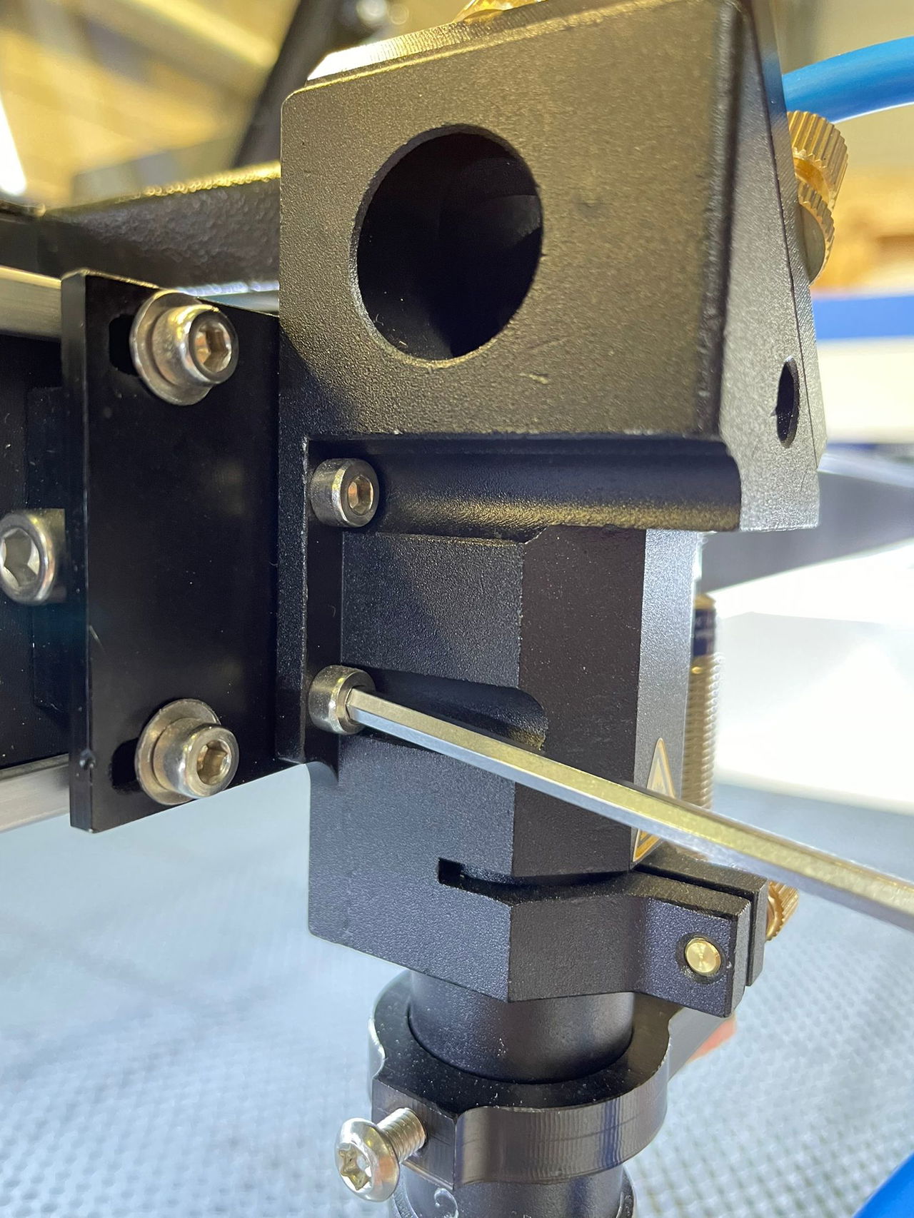
If the laser head is perpendicular, you can retighten the Allen bolts securely. If you have had to adjust the laser head perpendicularly, you should check the mirror alignment again. The laser beam now enters the laser head in another way and will also reach the lens with a different trajectory, causing the laser beam to land on your material differently.
If you cannot work this out, please send us a [ticket](/en/contact) and we will help you.
# The machine has problems with referencing
> When you turn on the machine, the machine should be referenced. The X and Y axes then go to the upper right corner and the table also goes to the 0 position. The axes then move toward a sensor. When the axes are at the sensor, the axes know where their zero point is. From this zero point, the machine knows where the limit is and where the axis must stop to avoid collisions with the body of the machine.
## Why do you have to reset the machine when you turn it on?
[Section titled “Why do you have to reset the machine when you turn it on?”](#why-do-you-have-to-reset-the-machine-when-you-turn-it-on)
When you turn on the machine, it needs to be referenced. The X and Y axes then move to the top right corner and the Z-axis goes to the 0-position. The axes go towards a sensor. When the axes reach the sensor, the axes know where their zero point is. From this zero-point, the machine knows where the limit is and where the axes must stop to avoid collision with the machine body.
If referencing is not done or not done properly, the axes do not know where they are positioned in the working area and how far they can continue moving sideways, forwards or backwards. This can cause collisions with the machine body.
Every machine starts up in a so-called ‘emergency state’, as shown by the red signal light on the machine. Depending on the type of machine, the reset button may be located in a particular spot:
* [BRM Slim](https://www.brmlasers.com/product/slim-1300?utm-source=support-site): on top, right above the display, the blue button with a LED.
* [BRM Original](https://www.brmlasers.com/product/pro-1300?utm-source=support-site): on the switch panel on the right side, the silver button with a green LED.
* [BRM Pro](https://www.brmlasers.com/product/pro-1300?utm-source=support-site): on the switch panel on the right side, the silver button with a blue LED.
* [BRM Budget](https://www.brmlasers.com/product/slim-1300?utm-source=support-site): on top, right above the display, the blue button.
**PLEASE NOTE! The reset button on the display is different, it is not needed for these actions.**
Because the machine wants to do the referencing during start-up, the reset button needs to be pushed immediately, so it has clearance to do that. If not, the machine will try to refer for some time (indicated by the pop-up on the screen) but will fail.
## The axis stops too early / The axes stop too early
[Section titled “The axis stops too early / The axes stop too early”](#the-axis-stops-too-early--the-axes-stop-too-early)
Do the axes stop before the sensor is reached? Then the sensor(s) may have moved, and the magnet (BRM Original) may have moved too. If the axis stops / the axes stop too early, the machine sees this as a new zero point. As a result, the laser head can move too far to the side or front of it, which can cause it to collide. This problem needs to be fixed before you can use the machine.
Make sure that the sensor and magnet (if there is one) are not displaced. If the magnet is dirty, clean it. Check whether it is still intact; if it has a crack, it needs to be replaced.
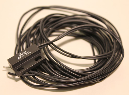
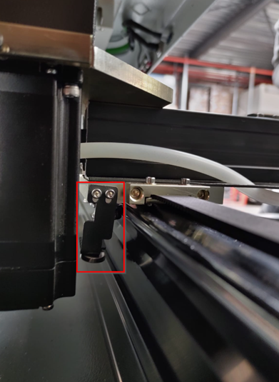
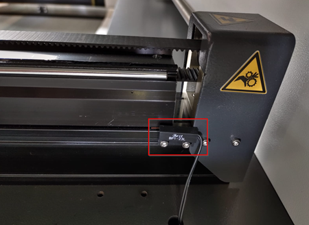

BRM Budgets and Slims have a switch sensor with a silver lever. Check that the lever has not adhered. If necessary, bend it back slightly. If this does not solve the problem, the sensor may be defective. If the lever has broken off, the sensor will have to be replaced.
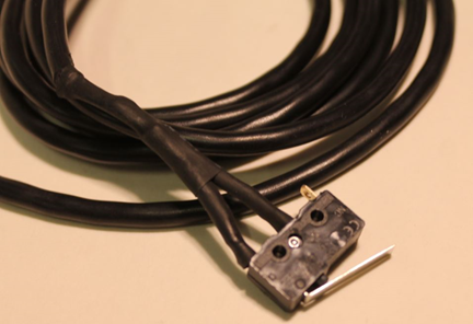
| 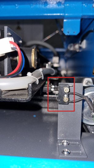 | 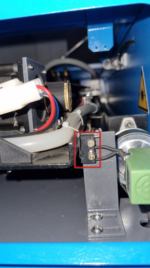 |
| ----------------------------------------------------------------------------------------------- | ----------------------------------------------------------------------------------------------------- |
| | |
The [BRM Pro](https://www.brmlasers.com/product/pro-1300?utm-source=support-site) has optical gate sensors. When the sensor is connected, a red light in the sensor is on. On the X- and Y- axes there is a small metal plate, which fits into the opening of the sensor. The sensor registers this so the axes will stop. If a problem occurs, the small metal plate may be slightly bent. See if bending the small metal plate solves the issue.
If the axis does not move towards the sensor, it may be that the sensor is dirty. Clean the sensor with a damp cloth.
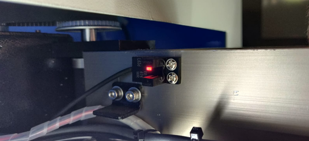
## The axis does not stop / The axes do not stop
[Section titled “The axis does not stop / The axes do not stop”](#the-axis-does-not-stop--the-axes-do-not-stop)
Is one of the axes not stopping and does it seem as if it wants to continue while reaching the sensor? Then the sensor does not notice the axis is already at the sensor. On a machine with a stepper motor, you will hear a rattling noise, indicating that the axis wants to continue. Turn off the machine to avoid breaking anything. On a machine with a servo motor, you will hear a bang. The motor is de-energized. The corresponding axis will then no longer move.
The cause may be a defective sensor or a broken cable. It is also possible that the magnet (in the case of the BRM Original) has become loose and is not detected adequately. If there has been a fire in the machine, the magnet may have lost its strength, causing the sensor not to notice it and allowing the axis to move too far. If there has been a fire, you should replace the magnets in the machine to ensure that this problem does not occur. It might also be that the magnet is dirty, then please clean it.
With the optical sensor, the small metal plate that must pass through the opening may not be aligned correctly. As a result, the small metal plate is not detected and the axis moves too far. Turn the machine off. Move the axis towards the sensor manually and check whether the small metal plate passes through the sensor correctly. If not, you can carefully bend the small metal plate. Also, check that nothing has broken off.
## The machine does not reference / The machine does not reference all axes when performing the reference
[Section titled “The machine does not reference / The machine does not reference all axes when performing the reference”](#the-machine-does-not-reference--the-machine-does-not-reference-all-axes-when-performing-the-reference)
Are all doors and covers closed? You cannot reference when a door / cover is open. With an unclosed door / cover, the machine will be in a secured state preventing the axes from moving and the laser from working. Check whether the emergency stop is pressed. Press the emergency stop. After pressing, turn the emergency stop by one-quarter clockwise so it rises again. Then press the reset button. Try referencing again.
If these tips don’t resolve the problem, please send us a [ticket](/en/contact) so we can take a look from there and possibly schedule a technician to solve the issue.
# The Red Pointer of my BRM Original is no longer visible
> If you have a BRM Original then chances are you have a Red Pointer. The Red Pointer allows you to see a guide line which can be useful when you want an indication of approximately where you are going to cut or engrave.
If you have a BRM Original, chances are you have a red pointer. The red pointer allows you to see a guideline that can be useful when you want an indication of where you will be cutting or engraving.
The red pointer follows roughly the same path as the laser beam with which you cut / engrave. But these two elements must be seen as independent of each other. When adjusting mirrors, for example, the guideline is never used as an indication. Also, the guideline can suddenly deviate without affecting the laser beam you are cutting / engraving with.
## How do I adjust the red pointer?
[Section titled “How do I adjust the red pointer?”](#how-do-i-adjust-the-red-pointer)
First, check if the laser power switch on the right-hand side of the laser machine is on. If it is on, it is important to check the mirror alignment completely. If the alignment is incorrect, the guideline may not be visible.
After you have checked the mirror alignment please look further. If you have had to adjust the mirror alignment, then check whether the guideline is visible after aligning the mirrors.
If the guideline is still not visible, position the laser head in the lower right-hand corner of the machine. Stick a piece of masking tape on the work area and pulse. Leave the laser head in place but put the table at the bottom of the machine. Take the lens shaft out of the laser head. Now you can adjust the red pointer.
The moment you open the door where the red pointer is, the guideline will disappear. So you have to guess and adjust in several small steps. Close the door after adjusting a little bit and see if the red dot appears on the piece of masking tape.
There are quite a few bolts on the red pointer mount. In the photo below, you can see that some of the bolts have a green checkmark. Use these bolts to adjust the red pointer. Do not use the other bolts.
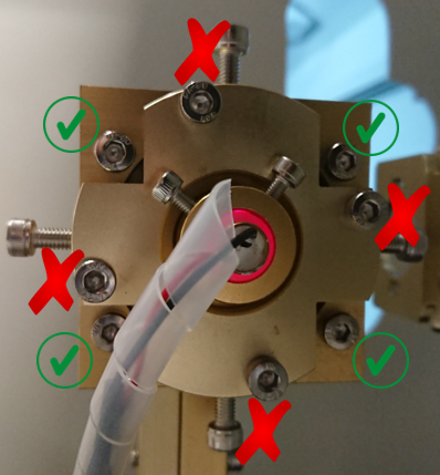
The bolts work together: if you adjust one bolt, you must also adjust a second bolt. When you rotate the bolts on the top or bottom as a set, you change the height of the guideline. Adjusting both bolts on the left or right as a set causes the guideline to move to the left or right.
If you notice you cannot continue to rotate the bolts in or out, use the one on the opposite side. For example, if you want to tighten the bolts on the right side but can’t, you can slightly unscrew the bolts on the left side.
## It doesn’t work, now what?
[Section titled “It doesn’t work, now what?”](#it-doesnt-work-now-what)
If you have the mirror alignment all sorted out and still can’t get the red pointer to align, you could check to see if the red pointer comes on when the door to the laser source is closed. Make sure the laser power switch is on. Get a camera or use your mobile’s camera. Make sure you can make a video.
Position the camera or telephone near the red pointer, facing it. Make sure the camera is recording. Close the door and leave the door closed for a moment. Then open the door and check the video. Usually, you will see a red glow on the video: that is the red pointer. If this glow is missing, please create a [ticket](/en/contact) and we will help you.
# The Y-axis of my BRM Budget does not work
> The Y-axis of my BRM Budget does not work
Troubleshooting guide for the [BRM Budget](https://www.brmlasers.com/product/slim-1300?utm-source=support-site) Y-axis.
## Please follow these steps if the Y-axis of your [BRM Budget](https://www.brmlasers.com/product/slim-1300?utm-source=support-site) does not work
[Section titled “Please follow these steps if the Y-axis of your BRM Budget does not work”](#please-follow-these-steps-if-the-y-axis-of-your-brm-budget-does-not-work)
When the Y-axis of the [BRM Budget](https://www.brmlasers.com/product/slim-1300?utm-source=support-site) does not work, first press the emergency stop. Then turn the emergency stop, clockwise. The emergency stop rises. Click on the Z/U button on the display. Go to **Axis reset+** and press the **\[Enter key]**. Choose **XY axis reset**. The axes will now reset, back to the top right corner.
The next step is to try to move the Y-axis by hand. If it can be moved freely, there is no tension on it. Lower the table a little. On the right, you should see two switches. These are the switches you flip when you want to work with the rotation unit. Both switches must be in the same direction.
Flip both switches over and back again. Now try to move the Y-axis again. Is there any tension now? If not, flip the switches. Is there any tension on the Y-axis now?
If there is still no tension on the Y-axis, please submit a [ticket](/en/contact) so we can help you out.
If during the first moment of moving the Y-axis by hand, you feel tension and cannot move it, the driver may malfunction. Open the door of the electrical cabinet on the right side of the machine. In the electrical cabinet, you will find drivers. These are usually 3 black drivers that are placed next to each other on the right side of the electrical cabinet. Make sure you don’t touch anything, this can cause dangerous situations.
NOTE!!!
High voltage is lethal. Only qualified people may carry out these operations.
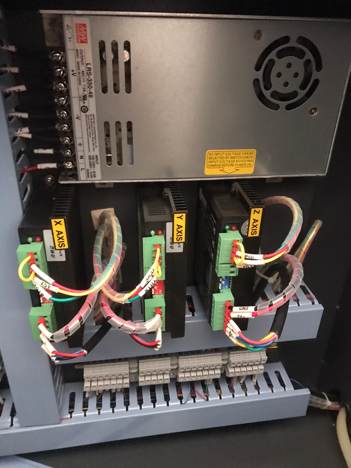
There are two LED lights on the drivers, a red light and a green light. Usually, only the green light is on while the red light is off. When the red light is on, it usually flashes several times, often either 3, 4 or 7 times. The red light indicates that there is a problem.
Please send us a [ticket](/en/contact) if you notice the red light is on, so we can help you out. We would also like to know how often the red light flashes.
# The Y axis of my BRM Original is not working
> If the Y axis of your BRM Original is not working there could be a couple of things going on. When you start the machine then press the reset button on the switch panel. The axes now drive to the right rear of the machine. After the machine does the reset the red alarm light goes out.
Troubleshooting guide for the [BRM Original](https://www.brmlasers.com/product/pro-1300?utm-source=support-site) Y-axis.
If the Y-axis of your [BRM Original](https://www.brmlasers.com/product/pro-1300?utm-source=support-site) is not working then there could be a couple of things going on. When starting the machine, press the reset button on the switch panel. You will find the switch panel on the right hand side of the laser machine. The axes will now move to the right rear of the machine. Once it has completed the reset, the red light of the signal lamp will switch off.
If the red light of the signal lamp stays on after the reset is finished, the emergency stop may be activated. Push the emergency stop. You will find it above the display of the machine. After pressing the emergency stop, rotate it a quarter turn, clockwise. The emergency stop rises. Also, check if all doors and covers are closed. Push the reset button again.
If the Y-axis does work during the reset but runs into the side in the top right corner, please read the article: [the machine has problems with referencing.](/en/problems-and-solutions/co2-machines/the-machine-has-problems-with-referencing)
## Y/U switch
[Section titled “Y/U switch”](#yu-switch)
Check if the rotation unit is plugged into the connectors. If the rotation unit is plugged in, you will not be able to use the Y-axis. Unplug the rotation unit to be able to use the Y-axis.
If the red light of the signal lamp switches off after the start-up but the Y-axis does not work, the first thing to check is whether all the doors are closed. Next, look at the switch panel on the right side of the machine. On this panel, you will find a black switch that can either be set to the Y- or U- axis.
If the switch is set to the U-axis, the Y-axis will not move. The U-axis is used when you are working with the rotation unit. In that case the Y-axis should not work since it has been switched to the U-axis. However, if you are not working with the rotation unit, the switch should be on the Y-axis.
If the switch is set to the U-axis, it is best to turn off the machine. Set the switch to the Y-axis and restart the machine according to the normal procedure. If you switch the Y/U switch when the machine is on, the machine may have some difficulty doing so. That is why we advise you to turn off the machine when you flip the switch.
If the Y/U switch is in the correct position or adjusting it does not solve the problem, you can switch off the machine. Position the laser head in the middle of the work area by hand. This does not need to be very accurate, approximately in the middle is fine. Turn the machine on again, following the normal procedure. Check whether the laser head is now moving to the right rear of the machine.
## Driver
[Section titled “Driver”](#driver)
If the laser head only moves in the X-direction but not in the Y-direction, the next step is to open the door of the electrical cabinet on the right side of the machine. Make sure that you do not touch anything, as this can lead to dangerous situations.
NOTE!!!
High voltage is lethal. Only qualified people may carry out these operations.
In the electrical cabinet, you will find 3 drivers: 2 aqua-blue ones and 1 black one. They are located in the upper part of the electrical cabinet. On the left side of the driver, you can see two LED lights, a green and a red one. Under normal circumstances, only the green light is on. In case of a malfunction on the Y-axis, the red LED on the driver may be flashing. It can flash 4 or 7 times.
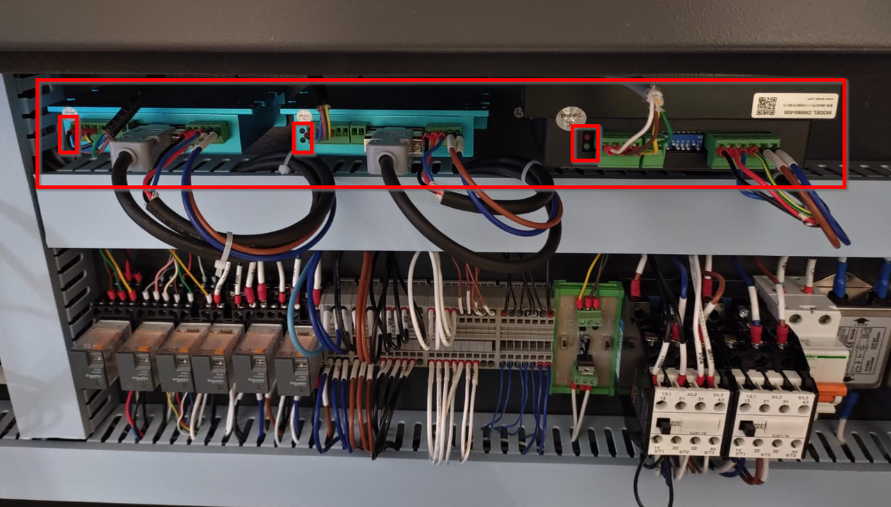
If the red light on the driver flashes, please submit a [ticket](/en/contact). We would like to know how often the light flashes. Whenever possible, we would also like to receive a video of the driver showing the flashing light.
## Relays
[Section titled “Relays”](#relays)
If only the green light is on and the red light is not flashing then the next step is to look at the relays.
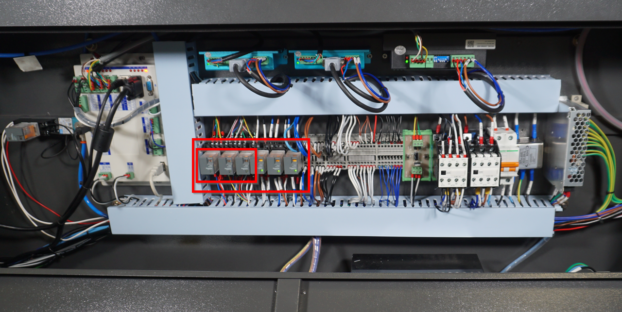
The relays allow switching between the U-axis and the Y-axis. If a relay does not work properly anymore, the switchover may fail so that the correct axis is not switched on.
In the [BRM Original](https://www.brmlasers.com/product/pro-1300?utm-source=support-site), the 3 relays on the left are for switching between the U- and Y- axes. You can pull out the blocks one by one and reinsert them. Restart the machine.
If this does not solve the problem, please send us a [ticket](/en/contact) with the steps you have already taken. We would also like to receive videos if you have made them. If the video is too large to be sent by e-mail, please send a WeTransfer link to: .
# The Y axis of my BRM Pro is not working
> The Y axis of my BRM Pro is not working.
Troubleshooting guide for the [BRM Pro](https://www.brmlasers.com/product/pro-1300?utm-source=support-site) Y-axis.
## Please follow these steps if the Y-axis of your [BRM Pro](https://www.brmlasers.com/product/pro-1300?utm-source=support-site) laser machine does not work
[Section titled “Please follow these steps if the Y-axis of your BRM Pro laser machine does not work”](#please-follow-these-steps-if-the-y-axis-of-your-brm-pro-laser-machine-does-not-work)
Check if the rotation unit is plugged into the connector. If the rotation unit is plugged in, you will not be able to use the Y-axis. Unplug the rotation unit to be able to use the Y-axis.
If the rotation unit is not plugged into the laser machine you can check if all doors are closed. All of them must be closed before the axes can move.
Next, press the emergency stop. After pressing the emergency stop, you can rotate it a quarter turn, clockwise. The button will come up now. Press the reset-button. You will also see that the signal lamp changed from red to green. Press the reset button.
After completing these steps and there is still no movement, you can check whether you can move the Y-axis manually. If it is difficult or impossible to move, it is under tension. If the Y-axis can be moved easily, there is no tension on it.
If there is no tension on the Y-axis, get the rotation unit, provided you have one. Connect the rotation with the plug. The socket for the plug is on the right-hand side of the machine. After connecting the rotation, remove the plug from the socket to disconnect the rotation. The time between connecting and removing the plug does not need to be long.
Listen for a click coming from the electrical cabinet when connecting the plug and removing it. If you don’t hear a click, you can open the door of the electrical cabinet. Make sure you don’t touch anything, as this can cause dangerous situations.
NOTE!!!
High voltage is lethal. Only qualified people may carry out these operations.
## Checking the relays
[Section titled “Checking the relays”](#checking-the-relays)
There are several relays in the electrical cabinet. When the rotation is connected, relay 100KA1 should switch. Check this by looking at this relay. Usually, a light on the relay will turn on or off when it switches. A relay is a square block, often transparent. There are several relays next to each other, on the left-hand side of the electrical cabinet.
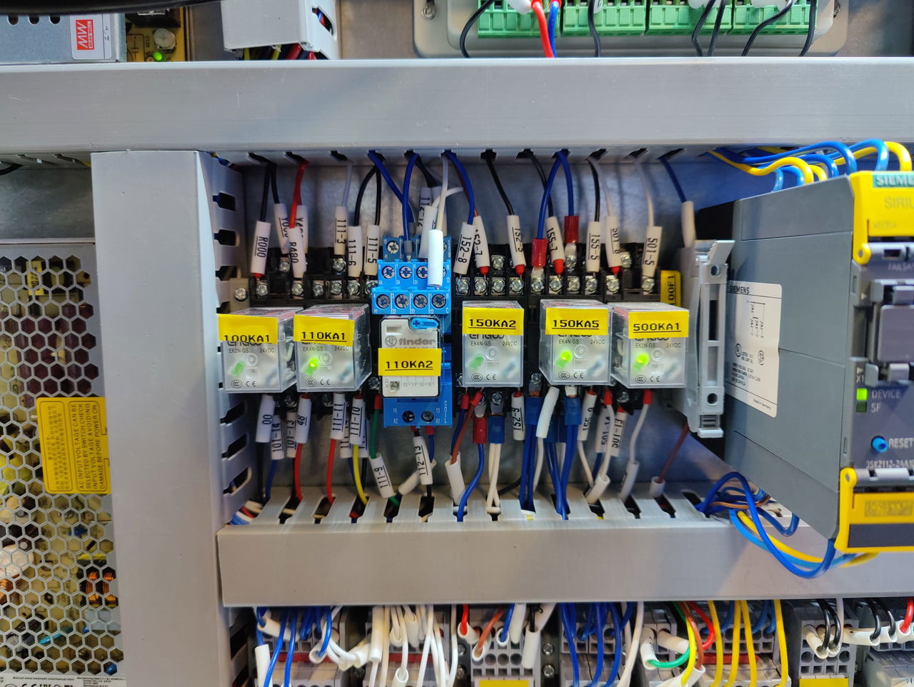
When the relays switch when you insert and remove the plug, you will also usually see that one of the drivers switches off and another driver switches on. The driver for the U-axis will switch on when you connect the rotation and the driver for the Y-axis will switch off at that moment. And vice versa. The drivers are blue and black and about 10 cm wide. They are on the right-hand side of the electrical cabinet. They often have stickers on them, look for the U-axis and the Y-axis driver.
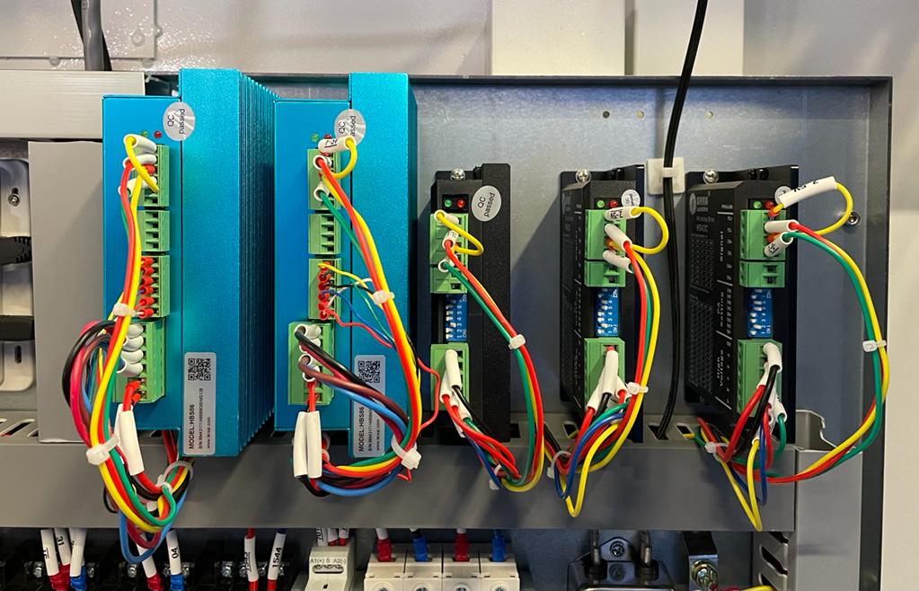
Should all this work fine but the problem persists, it is best to submit a [ticket](/en/contact) describing the steps you have already taken.
In case you don’t have a rotation unit or if the axis is powered and you have these problems, you can open the electrical cabinet. Make sure you don’t touch anything, as this can cause dangerous situations. Verify that the red light on the driver is flashing. If it is flashing then it is important to count how many times the light blinks. This may be 4 or 7 times.
Send in a [ticket](/en/contact) mentioning the steps you have already taken and how often the red light is blinking.
# The Y axis of my BRM Slim is not working
> The Y axis of my BRM Slim is not working.
Troubleshooting guide for the [BRM Slim](https://www.brmlasers.com/product/slim-1300?utm-source=support-site) Y-axis.
## Please follow these steps if the Y-axis of your BRM Slim laser machine does not work
[Section titled “Please follow these steps if the Y-axis of your BRM Slim laser machine does not work”](#please-follow-these-steps-if-the-y-axis-of-your-brm-slim-laser-machine-does-not-work)
If the Y-axis of the [BRM Slim](https://www.brmlasers.com/product/slim-1300?utm-source=support-site) does not work, first check if your rotation unit is plugged in if you have one. Unplug the rotation unit. Check if all doors are closed. All of them must be closed before the axes can move.
Next, press the emergency stop. After pressing the emergency stop, you can rotate it a quarter turn, clockwise. The button will come up now. Press the reset button. You will also see that the signal lamp changed from red to green.
After completing these steps, you can check whether you can move the Y-axis manually. If it is difficult or impossible to move, it is under tension. If the axis can be moved easily, there is no tension on it. If there is no tension on the Y-axis, get the rotation unit, provided you have one. Connect the rotation with the plug. The socket for the plug is on the right-hand side of the machine. After connecting the rotation, remove the plug from the socket to disconnect the rotation. The time between connecting and removing the plug does not need to be long.
Listen for a click when plugging in and unplugging. If you don’t hear a click, you can open the door of the electrical cabinet. Make sure you don’t touch anything, as this can cause dangerous situations.
NOTE!!!
High voltage is lethal. Only qualified people may carry out these operations.
## Checking the relays
[Section titled “Checking the relays”](#checking-the-relays)
There are several relays in the electrical cabinet. When the rotation is connected, relays 100KA1 and 100KA2 should switch. Check this by looking at the relays. Usually, a light on the relay will turn on or off when it switches. A relay is a square block, often transparent. There are several relays next to each other, on the left-hand side of the electrical cabinet.
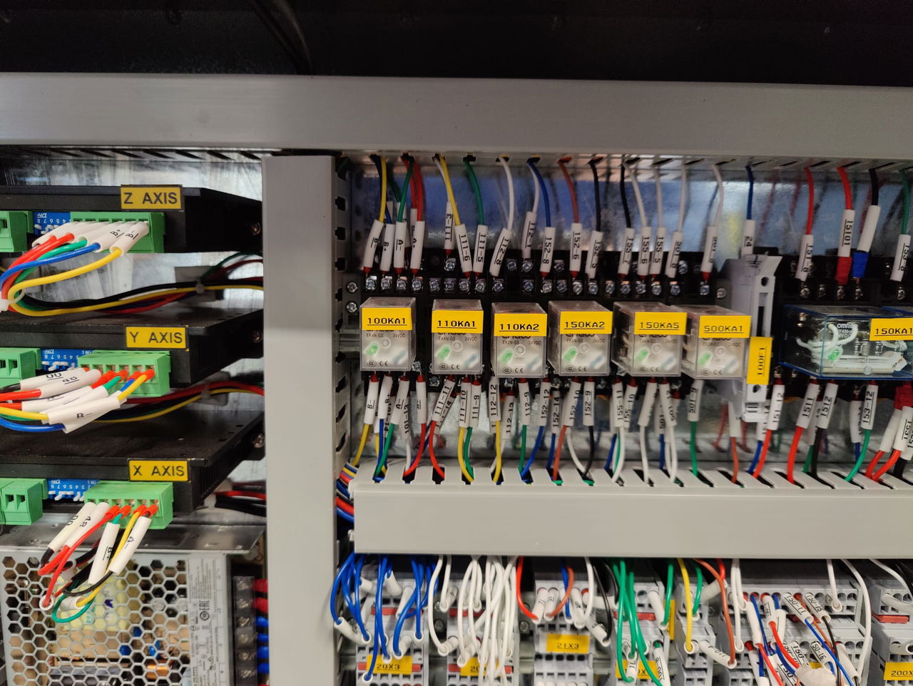
Should all this work fine but the problem persists, it is best to submit a [ticket](/en/contact) describing the steps you have already taken.
In case you don’t have a rotation unit or if the axis is powered and you have these problems, you can open the electrical cabinet. Make sure you don’t touch anything, as this can cause dangerous situations. Verify that the red light on the driver is blinking. If it is, then it is important to count how many times the light blinks. This may be 4 or 7 times.
Send in a [ticket](/en/contact) mentioning the steps you have already taken and how often the red light is blinking.
# The Z axis of the BRM Original is not working
> If the Z axis of the BRM Original no longer works that there are a number of things you could check yourself.
If the Z-axis of the BRM Original no longer works, there are a number of things you could check yourself.
## Check the signal lamp on the machine
[Section titled “Check the signal lamp on the machine”](#check-the-signal-lamp-on-the-machine)
First, check if the signal lamp on the machine is red. If it is red, the emergency stop is still activated. Press the emergency stop button and rotate it a quarter turn, clockwise. The emergency stop rises and the red light goes out. Make sure all doors and covers are closed. Press the reset button on the right side of the machine so the axes go to their zero position. When the machine is ready you can check if you can move the Z-axis by pressing the Z+ and Z-keys on the display of the machine.
## Is there any tension on the Z-axis?
[Section titled “Is there any tension on the Z-axis?”](#is-there-any-tension-on-the-z-axis)
At the bottom front of the BRM Original is a door. It provides access to the Z-axis timing belt. Open the door. The machine must be on to perform this test!
If you have opened the door, you will see a black timing belt. It goes to the 4 corners of the machine. Pull the belt carefully. If the belt moves easily, there is no tension on the Z-axis. If it is difficult or impossible to move it, there is tension on the axis.
If there is no tension on the Z-axis, then open the door of the electrical cabinet. You will find the door on the right side of the machine, at the bottom. Make sure you don’t touch anything, this could cause dangerous situations.
NOTE!!!
High voltage is lethal. Only qualified people may carry out these operations.
There are three drivers in the electrical cabinet. Two of the drivers are aqua-blue, and the third driver is black. The black driver corresponds with the Z-axis. There are two lights on the driver, a red one and a green one. In normal circumstances, only the green light on the driver is on. When the red light is on, it usually flashes. This indicates that there is a malfunction. If the green light is not on, there may be a defective power supply, for example.
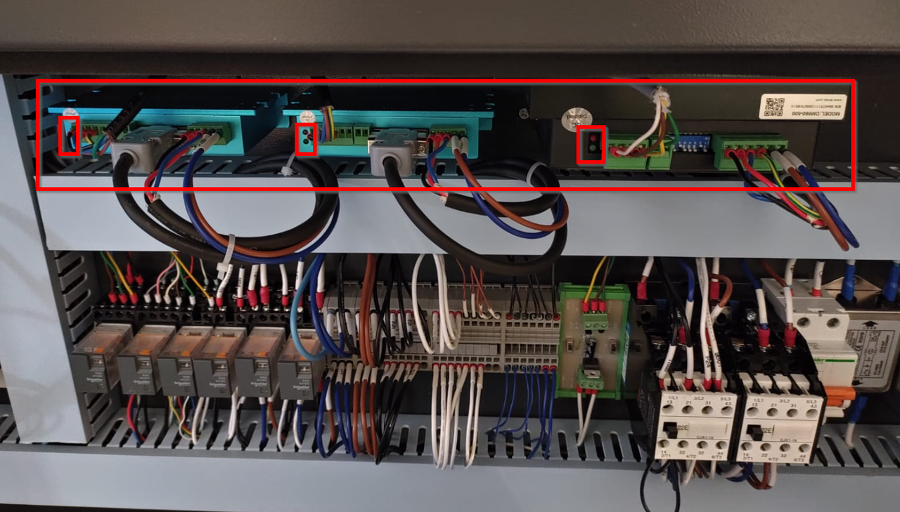
If the green light is not on or the red light on the driver is flashing, please send us a [ticket](/en/contact) explaining the steps you have already taken. If possible, also send us a video of the driver. If the video is too large to be sent by e-mail, please include a WeTransfer link in the e-mail. Send this to: .
If there is tension on the Z-axis, it may be that something is stuck or that the resistance is too high, causing the axis not to move. It is also possible that the motor has a problem.
First of all, check whether the timing belt still appears to be in good condition and whether there is anything between the timing belt that could cause a blockage. If that is the case, the blockage is usually in the area of the timing belt pulleys. If you see that there is indeed a blockage, try to carefully remove the blockage. Once you have removed it, you can try to move the Z-axis again.
If the axis still does not move, press the Speed button on the machine display. Set the **speed** very low, for example to 1 or 2. Try to move the axis again. If the axis now moves but does not move at a higher speed, the problem is most likely in the motor.
If this is the case, or if you cannot find the solution, please submit a [ticket](/en/contact) so we can help you out. We would also like to hear what steps you have taken.
# There are vibrations in the engraving lines
> Often vibrations in an engraving occur in the first and last part of the complete engraving. Vibration may also be present at the beginning of the engraving line.
## How come there are vibrations in the engraving lines?
[Section titled “How come there are vibrations in the engraving lines?”](#how-come-there-are-vibrations-in-the-engraving-lines)
Vibrations usually occur in the first and last part of an entire engraving. The vibration may also be present in the beginning of the engraving line.

When engraving, the X-axis has a different, higher, acceleration value than the Y-axis. This can cause vibrations. For example, the X-axis has an acceleration value of 8000 mm/s² and the Y-axis 500 mm/s². The X-axis goes back and forth at a certain speed. The Y-axis only requires moving a small distance to arrive at the next line. Because it only moves a short distance, there may still be some vibrations when the X-axis has already started the next line. This might be visible in the engraving.
## How can I reduce the vibrations so they are no longer visible?
[Section titled “How can I reduce the vibrations so they are no longer visible?”](#how-can-i-reduce-the-vibrations-so-they-are-no-longer-visible)
Check that all mirrors and the lens are fixed firmly in place. If a mirror or lens has come loose, the engraving line may show a vibration. Should anything have come loose, carefully retighten it so it is fixed in place again.
When you are about to engrave, you specify an **Interval**. The interval defines the space between the engraving lines and is normally between 0.06 and 0.12 (mm). Since it can affect the engraving line, check to see if the problem is reduced by adjusting the interval slightly.
You can view the user settings in the laser software. In LaserWorkV6 and RDWorksV8, you will find the **User** tab on the right side of the screen. Click on this tab. After that click on **Read**. Make sure that your laser machine is on and connected with the computer when you do this, otherwise, you will get an error message. Scroll down a bit to see the **Sweep parameters**.
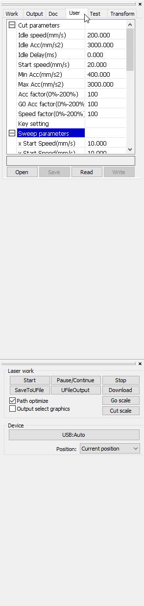
Observe the **Line shift speed (mm/sec)**. This is the speed at which the head moves to the next engraving line. Write down the value that is currently displayed. Change this speed, press **Write**, and send the task to the machine again. Check to see if this fixes the problem.
LightBurn also has this option. Go to Edit => Device settings. Make sure that your laser machine is on and connected with the computer when you do this, otherwise you will not be able to see the settings. If the machine is on and connected to the computer, it will read itself and you will see the values on the motherboard on the screen. Navigate to the **Engraving parameters**. Write down the value that is currently displayed. Change the **Line shift speed (mm/sec)**. Then press **Write** and send the task to the machine again. Check to see if this fixes the problem.
If this does not solve the problem, you can lower the acceleration value of the Y-axis a little. First, write down the number that is there now. If you have to change too much or it doesn’t help, enter the original values again and press **Write**.
Now check whether the belts still have the right tension and adjust if necessary.
For an article on adjusting and replacing the X- and Y-axis belts on the BRM Original, click [here](/en/problems-and-solutions/co2-machines/brm-original-belts-of-the-x--and-y--axes-adjustment-and-replacement).
In case you cannot solve the problem, please send us a picture of the engraving and the engraving line by [ticket](/en/contact) so we can assist you.
# I don't have a laser beam
> If you are not getting a laser beam on your material, there could be a number of things going on.
If you fail to get a laser beam on your material, there are a number of things that could be going on.
## What are the first steps I can take?
[Section titled “What are the first steps I can take?”](#what-are-the-first-steps-i-can-take)
First, check the mirror alignment. When checking that, it is easiest to put 2 layers of masking tape on the mirror on the left-hand side of the work area. Place the bridge closest to the laser source and press the ‘Pulse’ button on the display of the machine. If you get a burn mark here, then you can continue with the [mirror alignment.](/en/maintenance/optical-path/mirror-alignment)
If you do not get a pulse here, it is best to check the following aspects.
* Is the water chiller on?
* Is the alarm cable of the water chiller connected to the laser machine?
* Are all switches set correctly? Check that the laser power switch and auxiliary switch are set correctly.
* Check if the optics (mirrors and lens) are clean.
* On the BRM Original you should also check on the switch panel whether the Auto / Manual switch is set to Auto. If it is set to Manual, set the switch to Auto.
Note !!! High voltage is deadly
Only educated personnel is allowed to handle these steps
Also, check whether the laser source is in good condition and has no cracks or other damage. If the laser source is very dusty, you will need to clean it. Current chooses the path of least resistance and, in the case of a dusty source, will find a path through the dust so that the current does not flow through the normal path. The same goes for dirty cooling water. If the cooling water is dirty, you will have to replace it with clean cooling water. Read how to maintain the laser source [here.](/en/maintenance/optical-path/cleaning-the-laser-source) It is also important to check whether there is water in the outer glass tube. If there is water in it, the laser source is defective and will need to be replaced.
Should all this be in order and you have tested again without result, it might be that the laser source or the laser power supply is defective.
## How do I know whether the laser source is defective or if it is the laser power supply?
[Section titled “How do I know whether the laser source is defective or if it is the laser power supply?”](#how-do-i-know-whether-the-laser-source-is-defective-or-if-it-is-the-laser-power-supply)
Using a telephone with a camera and video function can be convenient. Turn the video function on and place the phone, with the camera aimed at the laser source, somewhere in the middle near the laser source. If the machine has a red pointer next to the laser source, you can place the phone a little further away so that the red light from the red pointer is not visible on the video.
Then start a small cutting program. After doing this you can watch the video. Usually, you will notice a pink glow inside the laser source. When this glow is visible, the laser power supply is working. If the glow is not pink but white then that is an indication the propellants in the laser source have evaporated / expired and the laser source will need to be replaced.
If there is a pink glow but no laser beam, the output beam may not be working properly. Check whether the lens in the laser source is intact and of even color. Should there be a crack or indentation in the lens or if the lens is not of even color, the laser source will need to be replaced.
|  | PLEASE NOTE!!! High voltage is lethal. Only qualified people may carry out these operations. |
| ----------------------------------------------------------- | -------------------------------------------------------------------------------------------- |
| | |
If all this looks right, you can check to see if the cathode looks good. The cathode is located at the tapered end of the laser source and is a metal tube. It is usually a plain-colored metal tube, silver or brass. Should the cathode be discolored, it is a sign of a well-used source and the laser source will need to be replaced.
|  |  |
| -------------------------------------------------------------------------------------- | --------------------------------------------------------------------------------------- |
| Evenly colored cathode, this is a new source. | Discolored cathode, this is a well-used source. |
If you do not see the laser source lighting up on the video, the problem is probably due to the laser power supply.
When you suspect the laser power supply is defective, you can open the bottom door at the back of the machine. There you will find the laser power supply.
The fan in the laser power supply will normally be on. Carefully check whether there is air flow. Do not touch the laser power supply!
There is a red LED on the laser power supply, which indicates whether the laser source is on. If the red LED is on / flashes, the laser source should be on. You can check this by pointing the camera of a phone at the LED. Make sure you turn on the video function. Close all the doors and run a simple cutting program or something similar so that you can see in the video whether the LED light turns on. Does the LED light go on / flash but there is no beam? Have you checked all the previous steps? Then the laser power supply is defective. Can’t see any red light? Then the power supply could be defective, but there could also be something wrong with the electrics. For example, a cable break.
Do you see the green light but no red light? Then the signal cables could be causing the problem. For instance, the alarm cable from the water chiller, the output cable from the motherboard to the laser power supply, etc. Nothing is lighting up and the fan is not running either? Then the power supply side, the 230 V, may be defective. This means that the laser power supply will not switch on.
If your machine has a red pointer, it is powered by the laser power supply. If the red pointer is not switched on and there is no laser beam, then either the laser power supply is switched off or defective. However, when the red pointer works, the laser power supply may not be fully functioning. It could still be the case that the laser power supply is defective.
The red pointer is supplied with 5 V from the laser power supply. This circuit is separate from the circuit that supplies power to the laser source. When the 5 V circuit is defective, it does not automatically mean that the circuit for the laser source is defective as well. However, it is common for both to be defective.
If you have gone through these steps and cannot solve the problem, please submit a [ticket](/en/contact) to BRM. If you have videos of the color of the laser source and the lights on the power supply, it is helpful to e-mail them. They often give us a lot of information. If the video’s are too large to send via mail, you can also send them via WeTransfer, to: .
Also, if you cannot work it out yet and do not know what steps to take or other questions arise, you can submit a [ticket](/en/contact) at any time.
# There is an offset in the cutting or engraving line
> When you are cutting something the line may suddenly jump a little bit. Suppose you are cutting a square and suddenly the horizontal line (X-axis) jumps a little bit. Then there is a problem in the Y-axis. The same is true in reverse, if there is a stagger in the vertical line (Y-axis) then there is a problem on the X-axis.
When cutting something, the line can suddenly jump off a bit. Say you are cutting a square and the horizontal line (X-axis) shifts a little. Then there is a problem with the Y-axis. The same applies in reverse. If there is a shift in the vertical line (Y-axis) then there is a problem with the X-axis.
## Check the distance between the lines
[Section titled “Check the distance between the lines”](#check-the-distance-between-the-lines)
It is important to check the distance between the lines. That can correspond to the spacing of the teeth of the timing belt. Usually, the length of a tooth is indicated on the timing belt. For example, if it says 25HTD-3M on the belt, it means the length of a tooth is 3 mm. If the deviation in your work is also 3 mm, the first step is to check whether the timing belt is still completely intact. Also, check whether all the teeth on the belt are still there and whether they are pointy. If one or more teeth are worn flat, the belt may slip.
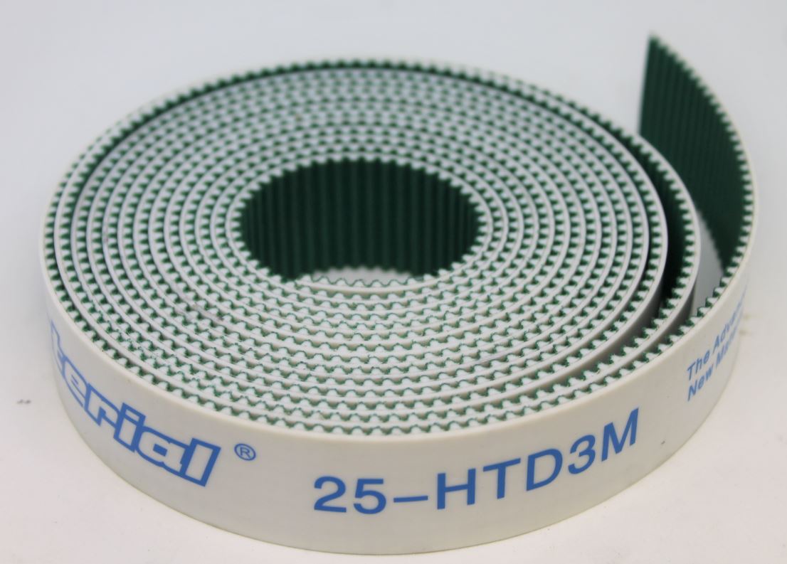
If the belt is intact, the next step is to check whether the timing belt pulleys are still in good condition. If the teeth on the timing belt pulley are no longer pointy, the timing belt can also slip here and skip a bit.
If the timing belt or the timing belt pulley is no longer in good condition, they will have to be replaced.
## Is the timing belt pulley fastened properly?
[Section titled “Is the timing belt pulley fastened properly?”](#is-the-timing-belt-pulley-fastened-properly)
If the length of the deviation does not correspond to the length of the teeth of the belt, it may be that the timing belt pulley is not secured properly. The timing belt pulley has a locking bolt. The axis over which the timing belt pulley sits has a flat surface. The locking bolt secures the timing belt pulley in this area. If the locking bolt has loosened somewhat due to vibrations, it can rotate further than it should, causing slack. The same applies here: if the deviation is on the X-axis, the problem is on the Y-axis and vice versa.
To check this, it is important that the machine is on but not running a program. The motors are powered. Now check whether you can turn the timing belt pulley and whether there is any slack. Usually, you cannot turn the timing belt pulley. If a timing belt pulley does turn, there is slack in it. To solve slack you have to tighten the locking bolt in the timing belt pulley. Also, check if the timing belt is still intact, the bolt might have loosened a bit unnoticed and damaged the timing belt.

When you find a timing belt pulley with slack, you can check the other timing belt pulleys just to make sure they are all properly secured.
## The timing belts and timing belt pulleys seem fine, now what?
[Section titled “The timing belts and timing belt pulleys seem fine, now what?”](#the-timing-belts-and-timing-belt-pulleys-seem-fine-now-what)
If the timing belts and the timing belt pulleys seem to be in good condition and the locking bolts in the timing belt pulleys are all secured, there may be slack in the motor or the bearings.
If that is the case, please submit a [ticket](/en/contact) indicating what you have already tried so we can help you.
# How to connect oxygen to the BRM 90130-X or the BRM Budget 90130-X
> A 150 W laser source by itself does not have enough power to cut through metals. By adding oxygen you feed the fire allowing you to put enough power into the material and cut.
## Why does oxygen need to be added when cutting metals?
[Section titled “Why does oxygen need to be added when cutting metals?”](#why-does-oxygen-need-to-be-added-when-cutting-metals)
A 150 W laser source on its own has too little power to cut through metals. By adding oxygen, you feed the fire so you can get enough power into the material and cut it. By doing so, you compensate for the power of the laser source.
## What is the required degree of purity for the oxygen?
[Section titled “What is the required degree of purity for the oxygen?”](#what-is-the-required-degree-of-purity-for-the-oxygen)
The minimum recommended degree of purity for the oxygen is 3.5 (99.95 %). You want your oxygen to be as pure as possible. That allows you to cut faster and also gives you a better result. If you take oxygen with a purity degree of less than 99.5 %, getting a better result becomes a real challenge. The production speed will also have to be reduced. In case of cutting problems that you cannot solve, choosing pure oxygen (with a higher purity degree) can be the solution.
## How do I connect oxygen?
[Section titled “How do I connect oxygen?”](#how-do-i-connect-oxygen)
The BRM90130-X and the BRM Budget90130-X both have an O₂ connection at the back of the machine. Do not confuse the oxygen connection with the air connection! The air connection is the connection for the air pump.
The oxygen must be connected to the O₂ connection. A maximum of 8 bar oxygen is allowed. That means you must use a reducing valve to reduce the oxygen from the tank to a maximum of 8 bar. This reducing valve is not included in the machine.
Most oxygen tanks have a screw connection. The machines do not work with a screw connection but with a 6 or 8 mm push-in fitting. Everything built into the machine is taken care of by BRM, everything from the push-in fitting to the oxygen cylinder is not provided by BRM.
The oxygen pressure cannot be regulated in the machine. You need to regulate it at the oxygen tank with the reducing valve. The pressure is allowed to be 8 bar at the most, but it can also be less. You can shut off the oxygen completely between every cutting task to ensure no oxygen escapes. But this is not necessary.
If your machine is in metal mode, it will automatically start using oxygen.
## What do I need to do to safely disconnect the oxygen tank?
[Section titled “What do I need to do to safely disconnect the oxygen tank?”](#what-do-i-need-to-do-to-safely-disconnect-the-oxygen-tank)
If you need to change the oxygen tank, first close the tank completely. Then press the dot button on the display of the laser machine. The oxygen line is opened for a moment. This will vent the lines. After a few seconds turn it off again. You can now disconnect the hose. Unscrew the reducing valve and place it on a new oxygen tank.
Before connecting or disconnecting an oxygen tank, it is important to be aware of the potential dangers and how to deal with any problems.
If you cannot work this out, please send us a [ticket](/en/contact) and we will help you.
# What metals can I cut with my BRM 90130-X or BRM Budget 90130-X?
> I have a the BRM90130-X or a budget90130-X and I would like to know if I can cut certain metals. Please note that the machine must be suitable for cutting metal! If the machine is not suitable for cutting metal and you try to do it anyway, the machine may break down.
I have a BRM 90130-X or a Budget 90130-X and I would like to know if I can cut certain metals. Please note that the machine needs to be suited to cut metal! If it is unsuitable for cutting metal and you try to do it anyway, the machine may break down.
Not sure whether your machine is suitable for cutting metal? Then send your question with a picture of the machine’s type shield via a ticket to BRM, and we will check it for you.
## Metal mode
[Section titled “Metal mode”](#metal-mode)
To cut metal with your machine, you will have to switch it from the acrylic mode to the metal mode. If you want to cut metal in the acrylic mode, it won’t work.
When you set the machine in metal mode, you also need to use the right lens. The lens you use to cut metal is only suitable for machines that can actually cut metal. This lens is larger than the lens you use to process wood and other materials, you can identify by this that it is a lens specifically for cutting metals.
Also, in metal mode, the laser head adjusts focus automatically. That is necessary because the focus distance from the lens to metal requires exact accuracy. Due to the required high gas pressure, you move your material, so the focus height has to be adjusted continuously. When the machine is in metal mode, the head will follow and adjust this itself. As a result, the focus height always remains correct.
## What requirements must a metal have in order to be cut?
[Section titled “What requirements must a metal have in order to be cut?”](#what-requirements-must-a-metal-have-in-order-to-be-cut)
In general, there are a few types of metal that may and can be cut with the BRM 90130-X and BRM Budget 90130-X.
The following metals can be cut.
* All types of iron.
* Non-alloy steels. Stainless steel is an exception. This is an alloy but can be cut.
Iron, steel and stainless steel are all very pure metals. The laser beam has the right power and absorption at the wavelength, which means the laser beam is not being reflected, but absorbed. As a result, these metals can be cut. These metals can be cut, up to a thickness of 1.25 mm.
If you do want to cut any thicker, there is a high risk of not getting through your material. There is also a risk that the cut will not turn out nicely. You may get a wide cutting line. You bring too much heat into your metal, causing it to melt uncontrollably.
The metals below cannot be cut.
* Precious metals. Such as gold, silver, etc.
* Alloys.
* Aluminium.
With these materials the absorption wavelength is different, so the laser beam will reflect instead of being absorbed. As a result, you cannot cut these metals.
## Why does oxygen need to be added when cutting metals?
[Section titled “Why does oxygen need to be added when cutting metals?”](#why-does-oxygen-need-to-be-added-when-cutting-metals)
A 150 W laser source on its own has too little power to cut through metals. By adding oxygen, you feed the fire so you can get enough power into the material and cut it. By doing so, you compensate for the power of the laser source.
## What is the required degree of purity for the oxygen?
[Section titled “What is the required degree of purity for the oxygen?”](#what-is-the-required-degree-of-purity-for-the-oxygen)
The minimum recommended degree of purity for the oxygen is 3.5 (99.95 %). You want your oxygen to be as pure as possible. That allows you to cut faster and also gives you a better result. If you take oxygen with a purity degree of less than 2.5 (99.5 %), getting a better result becomes a real challenge. The production speed will also have to be reduced. In case of cutting problems that you cannot solve, choosing pure oxygen (with a higher purity degree) can be the solution.
## Why do I need to use a different lens while cutting metal?
[Section titled “Why do I need to use a different lens while cutting metal?”](#why-do-i-need-to-use-a-different-lens-while-cutting-metal)
The lens used to cut metal has a different coating from the one you use for cutting wood and acrylic, for example. The coating of the metal lens stops the reflections and scatter radiation that occurs when cutting metals. That prevents the laser beam from reflecting to the laser source. The coating of the lens you use with wood and acrylic, on the other hand, cannot, so the laser beam reflects to the laser source. Reflection will damage the laser source.
## Marking metals
[Section titled “Marking metals”](#marking-metals)
Engraving with a metal laser without laser spray is highly inadvisable. Not even with the metal lens and certainly not on metal mode. If you do try to mark a metal without adding laser spray, your material will burn and a crater may form. That causes the laser head to lower because the laser head wants to adjust the focus height. As a result, the laser head lowers too far because no material is detected. But the laser head continues to move back and forth and, as a result, will eventually collide when it suddenly encounters material.
To still be able to mark metal with the BRM 90130-X or BRM Budget 90130-X with the addition of a laser spray, you will have to set the machine in acrylic mode. That will disable automatic adjustment of the focus height. You can now start marking your material with the lens you usually use for wood and acrylic. You can use the Z- and Z+ to set the head to the correct focus height.
Do not mark metal without the use of a laser spray.
If you do mark metals without a laser spray and the laser source is damaged, this is not covered by warranty!
[Check this article about laser spray.](/en/materials-and-parameters/lasersprays/why-use-a-laserspray)
## How do I find the right parameters to cut metal?
[Section titled “How do I find the right parameters to cut metal?”](#how-do-i-find-the-right-parameters-to-cut-metal)
The parameters for cutting a metal come quite precisely. Metals have a certain melting temperature that must be taken into account.
Up to that value, you create a lot of burr at the top of your material. This is molten material. Burr is something you will continue to have until you get through your material.
Set your laser power to maximum (98 %) and add lots of oxygen, which may be as much as 8 bar. Select a high speed and decrease it in steps until you do get through your material. You must make the various cuts side by side. With metal, you cannot go over your cut again. When you heat metal and it cools down again, the material hardens which requires more power a second time. That is impossible, so you will need to make a new cut next to it. With regular steel, you may need a speed between 20 mm/s and 50 mm/s with full power and sufficient oxygen.
Iron is slightly easier to cut. Here you may already get through at, say, 80 mm/s with full power and enough oxygen. Of course, that also depends on the cleanliness and alignment of the mirrors and lens.
If it seems like the machine is welding instead of cutting, that may be due to the alignment of the mirrors. It could also be that the speed is a bit too high. Also, use enough oxygen. When using too little oxygen, this can also occur. 8 bar is the maximum the machine can handle, so you can certainly use that to cut nicely and fast.
If you use less oxygen, you will need to reduce your speed somewhat to still get a good result. Should you want to add less oxygen to save costs, you will probably be disappointed. Adding less oxygen means you need more time to cut out the product. As a result, you will still use as much or even more of it.
Finding the correct parameters is quite difficult when cutting metals because it requires great precision. Each metal has a different melting value, so the parameters of stainless steel, for example, cannot be copied one on one for iron.
When you get any craters in your material, you will have to increase speed. Too much heat is getting into the material, causing it to melt.
If a brownish edge appears along the cut, you can also cut a little faster. The heat cannot cool down fast enough, causing the edge to turn brown. You may also need to use a bit less oxygen.
If burrs form at the top of your material, it could be a sign of the correct speed but not enough oxygen. The oxygen is not blowing enough combustion downward. If you have burrs on the bottom of your material, you should be able to remove them easily with your finger. If that is not the case, you can cut just a bit faster.
If you have any further questions please feel free to create a [ticket](/en/contact).
# Software support
### LightBurn
***
[How can I load the machine profile into LightBurn?How can I load the machine profile into LightBurn?](/en/software-support/lightburn/how-can-i-load-the-machine-profile-into-lightburn)
[>](/en/software-support/lightburn/how-can-i-load-the-machine-profile-into-lightburn)
[How do i create a BRM machine in LightBurn (2.0 and above)?LightBurn is capable of importing vendor packages with machine profiles, how do i do that?](/en/software-support/lightburn/how-do-i-create-a-brm-machine-in-lightburn)
[>](/en/software-support/lightburn/how-do-i-create-a-brm-machine-in-lightburn)
[How do I create a machine profile in LightBurn (1.9 and earlier)?How do I create a machine profile in LightBurn?](/en/software-support/lightburn/how-do-i-create-a-machine-profile-in-lightburn)
[>](/en/software-support/lightburn/how-do-i-create-a-machine-profile-in-lightburn)
[How do I activate and deactivate my LightBurn license?How do I activate and deactivate my LightBurn license?](/en/software-support/lightburn/how-to-activate-and-deactivate-lightburn)
[>](/en/software-support/lightburn/how-to-activate-and-deactivate-lightburn)
[How to install LightBurn?Here you can read how to install LightBurn.](/en/software-support/lightburn/how-to-install-lightburn)
[>](/en/software-support/lightburn/how-to-install-lightburn)
### Software
***
[How to export files from Illustrator (.ai/.eps/.svg) so you can use them in LaserWorkHow to export files from Illustrator (.ai/.eps/.svg) so you can use them in LaserWork.](/en/software-support/software/exporting-files-from-illustrator-to-laserwork)
[>](/en/software-support/software/exporting-files-from-illustrator-to-laserwork)
# How can I load the machine profile into LightBurn?
> How can I load the machine profile into LightBurn?
If you have a Slim, Pro or new Open Bed laser, you received a USB stick with the machine that has the machine-specific LightBurn backup on it, including the machine profile. If you have LightBurn installed on another computer it is important that you reload this machine profile there as well to get the best cutting and engraving results.
Insert the USB flash drive into the computer so you can load the file right away. It is also always wise to save the backup to the computer, in case you lose the flash drive. It is also wise to save the license key of LightBurn, which you also find on the USB flash drive, somewhere on the computer, so you can always find it back.
Open LightBurn. On the right side of your screen you will find the “Devices” button.
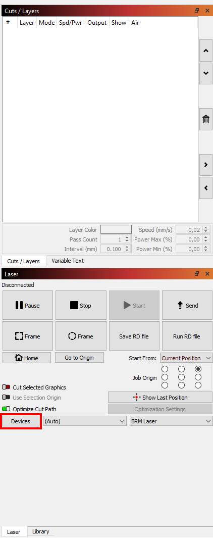
Click on it. Then choose ‘Import’.
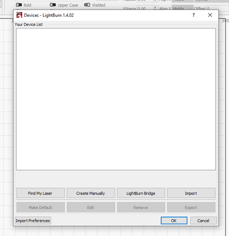
In the new screen that opens, you can look for the backup file. Select the file and click on Open.
This takes you back to the Devices screen. The screen now shows the serial number of your machine. Click on the name so that the line turns blue. Next, click Make Default and then click Ok. You have now successfully loaded the backup.
If you have any questions, you can always submit a [ticket.](/en/contact)
If you don’t have a machine profile yet then you have to create it manually. Through this [link](/en/software-support/lightburn/how-do-i-create-a-machine-profile-in-lightburn) you can read how to do that.
# How do i create a BRM machine in LightBurn (2.0 and above)?
> LightBurn is capable of importing vendor packages with machine profiles, how do i do that?
## Written explainer:
[Section titled “Written explainer:”](#written-explainer)
BRM Is a partner of LightBurn, the vendorpackage is downloadable here: [Download](https://cdn.brmlasers.com/support/Software/BRM_Lasers_All_Machines.lbvendor)
Note!
You cannot open the package in your operating system, which does not recognize .lbvendor files. Open it from LightBurn or drag and drop the file into LightBurn.
if you drag and drop the BRM package into LightBurn, the bundle selector will show up.
Choose the machine model(’s) you have by checking the boxes in front of the machine names. Then choose the material libraries of the laserpowers you have.
Then press the import button.
LightBurn will now show the machine in the machine list.
press okay.
Now you can use the machine in LightBurn.
## Video explainer:
[Section titled “Video explainer:”](#video-explainer)
If you have any questions, you can always send us a [ticket](/en/contact).
# How do I create a machine profile in LightBurn (1.9 and earlier)?
> How do I create a machine profile in LightBurn?
LightBurn works with machine profiles. If you have a Slim, Pro or a new Open Bed, you received a USB stick with the machine that contains the machine profile for your machine. Read [here](/en/software-support/lightburn/how-can-i-load-the-machine-profile-into-lightburn) how to load the machine profile into LightBurn.
If you do not yet have a machine profile then you can create one manually in LightBurn.
Open LightBurn. On the right side of your screen you will see “Devices.

Click on it. A new screen will open. Choose ‘Create Manually’.
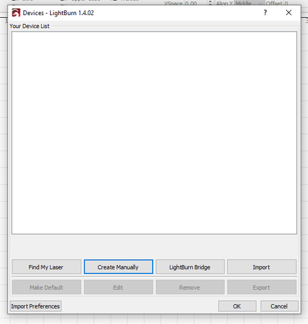
You will be guided through a number of screens where you have to make choices. We take you step by step through these choices.
First, you need to choose a controller. Scroll down and click on Ruida. Then click Next at the bottom of the screen.
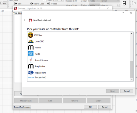
Next, you choose whether to connect your machine via USB or UDP. Normally, you choose USB here.
(If you choose UDP, you must enter a unique IP address here. You also enter that address on the machine and they should be exactly the same. Just make sure this IP address is static and not in use by anything else).
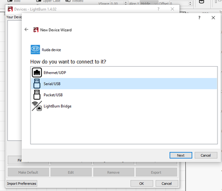
Click Next.
In this screen you can give your machine a name and also specify the size of your workspace. Do this in mm. For example, if you have a [Pro 900](https://www.brmlasers.com/product/pro-900?utm-source=support-site), enter 900 mm for the X Axis Length and 600 mm for the Y Axis Length.
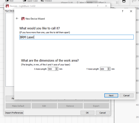
Then click on Next.
You must indicate here where the zero point of the machine is located. For all closed machines, the zero point is always on the upper right (Rear Right). For Open Bed machines, it is on the bottom right (Front Right).
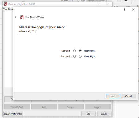
Click Next.
You will now see a small summary of everything you entered in previous steps.
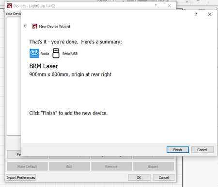
Check the list and click Finish.
You now see a machine in the Device list. If you click on it once, you select the machine. Then click on Make Default. Then click OK and you are done.
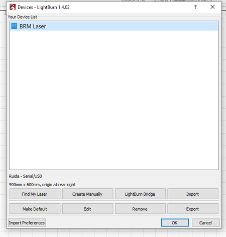
If you have any questions, you can always send us a [ticket](/en/contact).
# How do I activate and deactivate my LightBurn license?
> How do I activate and deactivate my LightBurn license?
If you have never used LightBurn before, or are installing LightBurn on another computer, you will first get the License and Trial page. Here you can enter and activate your license key if you already have a license key or you can, once, activate a free 30-day trial by clicking “Activate trial”.
If you already have a license key, enter it exactly, including the dashes, in the “License Key” box and then click the “Activate License” button below it. We recommend copying the key and pasting it into the License Key box.
You can return to this screen in LightBurn at any time by going to the menu and clicking Help > License Management.
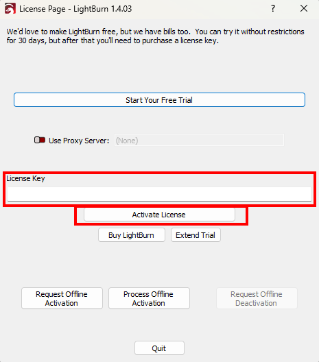
Click OK when you have activated your license or trial version.
Should you move to another computer in the future and want to work with LightBurn there too, it is important that you deactivate the license on the current computer first. You can enter the license on 3 computers. If you deactivate the license on one computer you have a free space on the license so it can be entered and activated again on a new computer.
If you have any further questions please feel free to send us a [ticket](/en/contact).
# How to install LightBurn?
> Here you can read how to install LightBurn.
First, you need to download the LightBurn software. You can do this [here](https://lightburnsoftware.com/pages/download-trial?utm_source=BRMLasers+support+portal\&utm_medium=article\&utm_campaign=How+to+install+LightBurn%3F\&utm_id=BRM+lasers).
You can install the software on a Windows or MacOs computer. Make sure you download the correct version.
After the download is complete you can install the software. In the explorer, go to the Downloads folder. There you will find a LightBurn-v.1.??? file. Double click on it. You are now going to install LightBurn.
You will get the following screen. Check ‘I agree to the license terms and conditions’ and click on Install.
You are now in the LightBurn installer. Select the icon ‘Create a desktop icon’ and click on Next.
In the next screen click on Install. Now wait until you get another screen where you have to take action.
In the screen ‘Completing the LightBurn Setup Wizard’, it is important that you check ‘Install FTDI serial driver (used by DPSs)’, otherwise you will not be able to establish a connection between LightBurn and your laser machine. Note that you don’t have this choice when installing on MacOS.

Also check the box next to ‘Launch LightBurn’. After installation, LightBurn will then open immediately. After you have checked the boxes, you can click on Finish.
A new screen will open, the ‘FTDI CDM Drivers’. Click Extract.
In the next screen, click Next.
On the License Agreement screen, click ‘I accept this agreement’. Then click on Next.
Then click Finish.
LightBurn is now installed.
[Here](/en/software-support/lightburn/how-to-activate-and-deactivate-lightburn) you can read how to enter your license key.
[This](/en/software-support/lightburn/how-can-i-load-the-machine-profile-into-lightburn) link shows you how to load your machine profile.
You do not have a machine profile yet? Then look [here](/en/software-support/lightburn/how-do-i-create-a-machine-profile-in-lightburn) to see how to create one.
It is important to know that with MacOS you can only connect between software and laser machine via Ethernet. Connecting via USB sometimes works but in general it doesn’t. With Windows, you can also use connection via USB, both options work equally well.
# How to export files from Illustrator (.ai/.eps/.svg) so you can use them in LaserWork
> How to export files from Illustrator (.ai/.eps/.svg) so you can use them in LaserWork.
Before starting, make sure Illustrator “Document color mode” is set to RGB:
File => Document color mode
## How to create a cutting line?
[Section titled “How to create a cutting line?”](#how-to-create-a-cutting-line)
Make sure that the line color of the whole cutting line is the same. In this example, the entire cutting line is blue:
Make sure that the whole shape is closed; if that is not the case, follow these steps:
Select the pen tool.
Click the anchor point of the shape you want to close.
Click the other anchor point to close the shape.
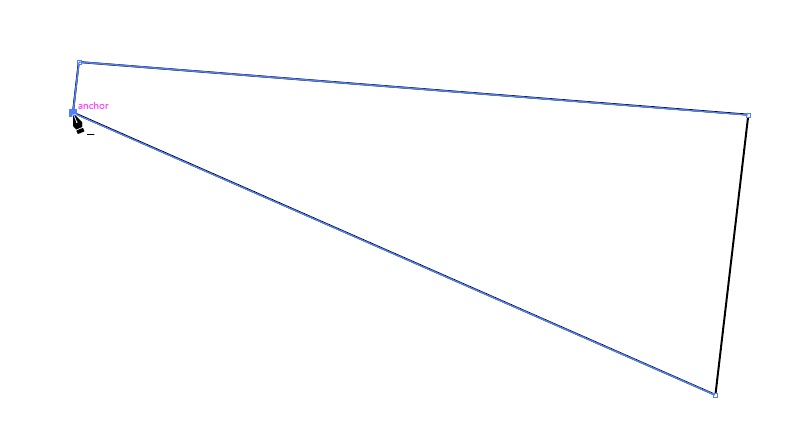
## How to create engraving lines?
[Section titled “How to create engraving lines?”](#how-to-create-engraving-lines)
Make sure the line color of the engraving lines is the same everywhere. In this example, all engraving lines are red:
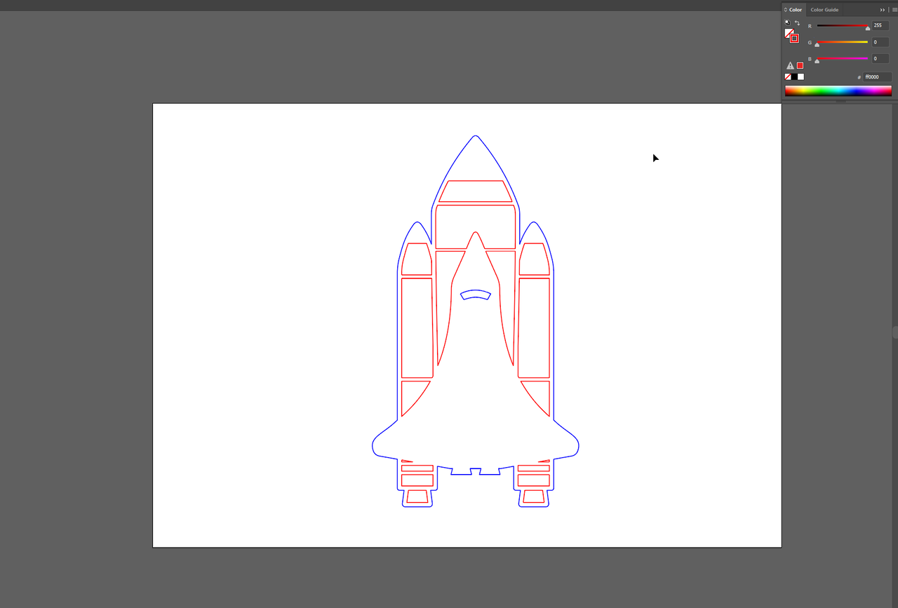
## How to save the file so it can be opened in LaserWork
[Section titled “How to save the file so it can be opened in LaserWork”](#how-to-save-the-file-so-it-can-be-opened-in-laserwork)
LaserWork operates with an old file format of Illustrator only.
File => Save as… Save the file as .ai.

From the screen that opens, choose Version: Japanese Illustrator 3
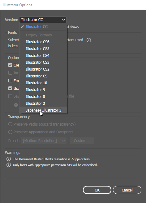
Click OK
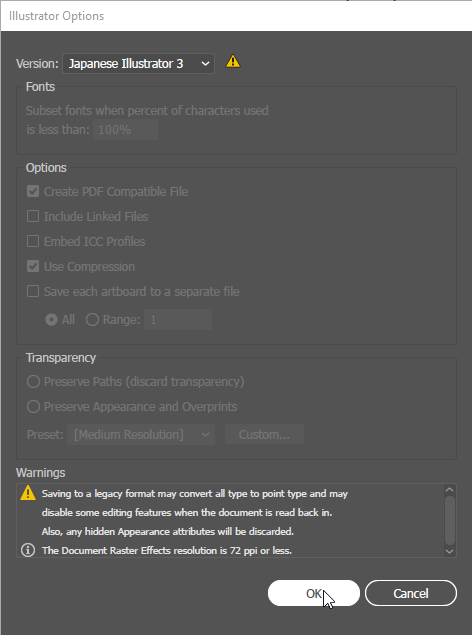
## Opening the .ai file in LaserWork
[Section titled “Opening the .ai file in LaserWork”](#opening-the-ai-file-in-laserwork)
Open LaserWork => Click import
Open the file you were just saving from Illustrator.
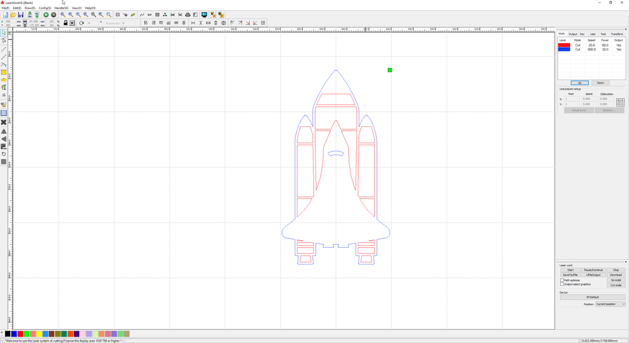
The colors you specified in Illustrator are now visible in LaserWork. These colors have now become layers in LaserWork, so all settings can be adjusted per layer.
# Tips and tricks
### Machines
***
[Can the laser machine and water chiller withstand the cold?A laser machine needs an ambient temperature of 15 °C to 33 °C. If the temperature in the room where the laser machine is located is below or above this, the machine will not work optimally. The result is less laser power and an inferior quality of the laser beam. This is of course reflected in your product, an engraving will look different and it will be a little more difficult to cut your material nicely.](/en/tips-and-tricks/machines/can-the-laser-machine-and-water-chiller-withstand-the-cold)
[>](/en/tips-and-tricks/machines/can-the-laser-machine-and-water-chiller-withstand-the-cold)
[How do I adjust the auto focus of my BRM Slim and Pro?The auto focus is a sensor that automatically selects the correct height relative to your material. This eliminates the need to manually determine the correct focus height between your material and the nozzle under the lens shaft.](/en/tips-and-tricks/machines/how-do-i-adjust-the-autofocus-of-the-slim-and-pro)
[>](/en/tips-and-tricks/machines/how-do-i-adjust-the-autofocus-of-the-slim-and-pro)
[These things are important to know before moving your laser machineYou like to use the machine but actually the machine needs to be moved. When the machine needs to be moved or relocated then there are some things you need to consider.](/en/tips-and-tricks/machines/it-is-important-to-know-these-things-before-moving-your-laser-machine)
[>](/en/tips-and-tricks/machines/it-is-important-to-know-these-things-before-moving-your-laser-machine)
[What can you do about reflection on your material?What can you do about reflection on your material?](/en/tips-and-tricks/machines/what-can-you-do-about-reflection-on-the-underside-of-your-material)
[>](/en/tips-and-tricks/machines/what-can-you-do-about-reflection-on-the-underside-of-your-material)
[What is a MSDS?It seems like the laser machine can machine all materials. Indeed, there are many materials that you can simply machine with the laser machine. But there are also exceptions.](/en/tips-and-tricks/machines/what-is-a-msds)
[>](/en/tips-and-tricks/machines/what-is-a-msds)
### Rotation system
***
[How do I find the circle pulse of the claw rotation BRM Original?The circle pulse is the ratio of the number of steps the motor has to do to rotate 1 x. Depending on the motor that is on the machine, the number the number of pulses is different and you also need a different value.](/en/tips-and-tricks/rotation-system/how-do-i-find-the-circle-pulse-of-the-chuck-rotation-brm-original)
[>](/en/tips-and-tricks/rotation-system/how-do-i-find-the-circle-pulse-of-the-chuck-rotation-brm-original)
[How do I make my Slim machine and rotation ready for use?When you want to start working with the Slim and rotation there are a number of steps to follow.](/en/tips-and-tricks/rotation-system/how-do-i-make-my-slim-machine-and-rotation-unit-ready-for-use)
[>](/en/tips-and-tricks/rotation-system/how-do-i-make-my-slim-machine-and-rotation-unit-ready-for-use)
# Focus height tools
> Here you can find more information about focus height tools.
If you lose your focal height tool or if you are afraid of losing it, you can always cut out a new one with your laser machine.
We have made the drawings. All you have to do, is load them into the software, put your material in the machine and cut the drawing. ‘Focustool steps’ is a triangle with a step every millimeter. You can let the nozzle of the laser head rest on it and then fix the lens shaft. ‘Focustool’ is a smooth triangle with a small notch every millimeter.
| | |
| ----------------------------------------------------------- | ----------------------------------------------- |
| [Focustool steps](/assets/docs/cutfiles/Focustool-steps.ai) | [Focustool](/assets/docs/cutfiles/Focustool.ai) |
# Can the laser machine and water chiller withstand the cold?
> A laser machine needs an ambient temperature of 15 °C to 33 °C. If the temperature in the room where the laser machine is located is below or above this, the machine will not work optimally. The result is less laser power and an inferior quality of the laser beam. This is of course reflected in your product, an engraving will look different and it will be a little more difficult to cut your material nicely.
## The ideal environmental temperature
[Section titled “The ideal environmental temperature”](#the-ideal-environmental-temperature)
A laser machine needs an environmental temperature of 15 °C to 33 °C. If the temperature in the room where the laser machine is located is below or above that, the machine will not work optimally. The consequences are less laser power and a lower quality of the laser beam. Obviously, you will see this reflected in your product. An engraving will look different, and it is more difficult to cut your material nicely.
## Too high a temperature
[Section titled “Too high a temperature”](#too-high-a-temperature)
If the temperature is too high, the laser machine stops automatically. The water chiller provides an overheating alert until the temperature drops sufficiently. An error indication also follows if the water temperature is too low. The water chiller produces a constant sound signal and the display of the water chiller shows an error code.
## Too low a temperature
[Section titled “Too low a temperature”](#too-low-a-temperature)
Temperatures lower than 15 °C may cause damage to the laser machine and/or water chiller. Is the water chiller plugged into the laser machine? If so, plug the water chiller into an external wall socket. Leave the water chiller on continuously as long as temperatures can get colder than 15 °C. Even when the laser machine is off.
Does it get colder than 5 °C? Leave the water chiller on continuously, connected to an external wall socket. And provide additional heating of the water to a minimum of 15 °C. For that, you can place an external heater between the hose of the water chiller (water chiller outlet to laser machine inlet). You can usually purchase an external heater in a pet shop or online.
Even with the external heater connected, the water chiller needs to be on continuously to make sure the cooling water cannot freeze.
Danger!!
Damage to the laser machine or water chiller due to the water temperature dropping below 15 °C is not covered by the warranty.
If you have any further questions, please feel free to create a [ticket.](/en/contact)
# How do I adjust the auto focus of my BRM Slim and Pro?
> The auto focus is a sensor that automatically selects the correct height relative to your material. This eliminates the need to manually determine the correct focus height between your material and the nozzle under the lens shaft.
Auto focus guide for the [BRM Slim](https://www.brmlasers.com/product/slim-1300?utm-source=support-site) and [BRM Pro](https://www.brmlasers.com/product/pro-1300?utm-source=support-site).
## What is the auto focus?
[Section titled “What is the auto focus?”](#what-is-the-auto-focus)
The auto focus is a sensor that automatically selects the correct height with regard to your material. This eliminates the need to manually determine the correct focus height between your material and the nozzle (the tip at the bottom of the lens shaft).
The auto focus in the [BRM Slim](https://www.brmlasers.com/product/slim-1300?utm-source=support-site) and [Pro](https://www.brmlasers.com/product/pro-1300?utm-source=support-site) works through an ultrasonic sensor that measures whether the distance between the sensor and the material is correct. The auto focus sensor emits ultrasonic sound waves. These ultrasonic sound waves hit your material and return to the sensor from there. That takes a certain amount of time. Based on this time, it can determine the correct focus height. It basically works like echolocation. When the sensor notices the right time between sending and receiving, it sends a signal to the main board indicating the focus height is correct.
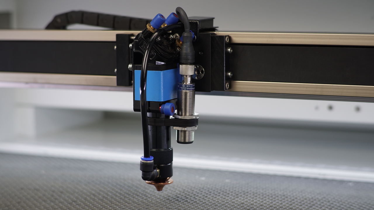
## Is the auto focus sensor able to detect all materials?
[Section titled “Is the auto focus sensor able to detect all materials?”](#is-the-auto-focus-sensor-able-to-detect-all-materials)
Because the sensor works with ultrasonic sound waves, you cannot use the sensor with all materials. Any materials that disturb ultrasonic sound waves, will not be detected by the sensor. Examples are foam, fabric, insulation material or other low-density materials. If the ultrasonic sound waves are disturb then they do not return to the sensor so the sensor does not detect the material and the table may rise too far. This results in a collision between the laser head and the material / the table.
Danger!!!
When the auto focus is used incorrectly or not for its intended purpose, warranty is void.
There are also certain types of wood that will disturb ultrasonic sound waves. These are often pieces of wood with a rough surface or bark. Additionally, cork does not cooperate with the ultrasonic sound waves and cannot be used with the auto focus. So don’t assume that the material you want to work with is also suitable for the auto focus function.
## Testing the suitability of your material
[Section titled “Testing the suitability of your material”](#testing-the-suitability-of-your-material)
When you are going to work with a new material you need to first test whether the material will be detected by the sensor.
Lower the worktable. Hold the material in your hands and put it under the auto focus sensor. Make sure it is actually under the sensor and that you keep it straight. If it is only under part of the sensor, it can still be mismeasured. If you move the material towards the sensor, the orange light at the top of the auto focus sensor should turn on. Make sure the auto focus sensor can’t detect your hand.
When the light on the auto focus sensor goes on, your material is detected, and you know you can use the auto focus function. You also hear a click when the light turns on.
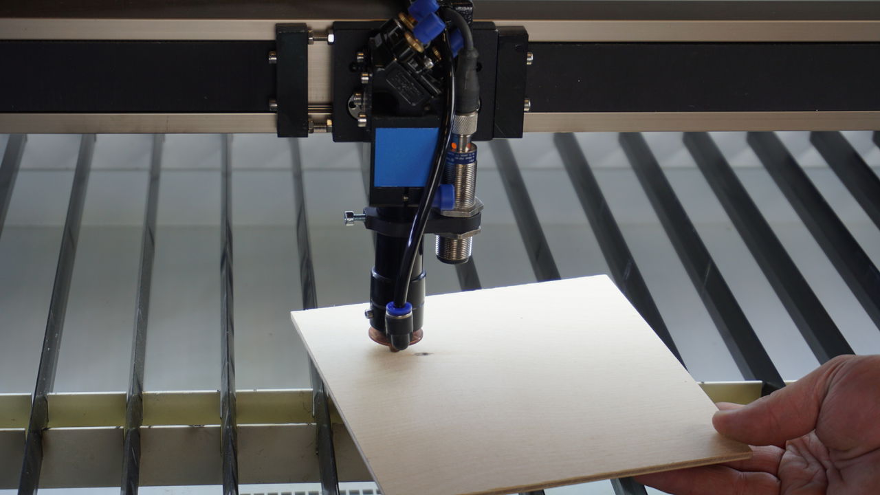
When the orange light does not go on while moving it towards the sensor, you cannot and should not use the auto focus function. Instead, you will have to determine the focus height manually. If you use the auto focus function anyway, the chance of a collision is very high. Should damage occur that way, it is not covered by any warranty.
Note!
The auto focus holder is set at the correct height by us. Make sure that you never reposition it as this can damage your laser machine!
Make sure the lens shaft is at the very top of the laser head. Do that by rotating the bolt on the laser head at the Pro. Rotate the bolt and hold the lens shaft. Position the lens shaft at the very top and re-tighten the bolt. On the Slim, there are two bolts on the right side of the laser head. You can unscrew the lower one while you are holding the lens shaft. Then move the lens shaft up and tighten the bolt again.
Press the ‘Focus’ button on the machine’s display. The table will rise and stop at the highest point. You will see that the distance between the table and the nozzle is still rather large. Rotate the knob again to lower the lens shaft. Make sure the nozzle (the tip of the lower end of the lens shaft) touches the table. Re-tighten the lens shaft.
Lower the table slightly. Place your material on the table. Make sure there is enough material under the sensor so that the sensor can spot the material. Press the ‘Focus’ button at the display again. Please keep your hand near the emergency stop so you can press it quickly if something goes wrong, especially if this is your first time working with this material.
If all goes well, the table stops moving and the orange light on the sensor is on. Look for a red dot, from the red pointer, on your material. Be aware, the key switch for the laser has to be turned to the right to be able to see the red dot. If you do not see that you are too close to the material. Should you see a large dot, you are too far away from it. Press the ‘Focus’ button again to see if that fixes the problem.
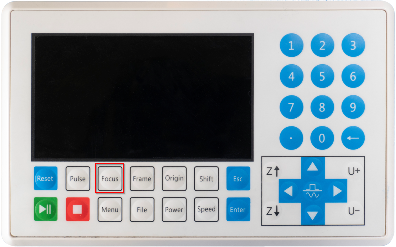
When the light on the auto focus sensor does not come on at all, regardless of the material you place under it, it might be that the plug at the top of the sensor is not properly fitted into the sensor. You can take the plug out and reattach it. There is a small pin in the plug that should fall into a hole in the sensor. In other words, it can only be inserted into the sensor in one way. Connecting the plug incorrectly and pressing too hard can break the pin, and the plug and cable need to be replaced. So make sure you do this properly.
If you can’t work things out, please feel free to submit a [ticket.](/en/contact)
# These things are important to know before moving your laser machine
> You like to use the machine but actually the machine needs to be moved. When the machine needs to be moved or relocated then there are some things you need to consider.
## Can I move / relocate the machine myself?
[Section titled “Can I move / relocate the machine myself?”](#can-i-move--relocate-the-machine-myself)
We can’t answer that right away. Please check a few things for yourself.
* Can you disconnect the machine yourself?
* Can the machine be moved out and into its correct place at the other location in its entirety?
* Is there enough knowledge to reconnect the machine and adjust everything correctly?
* If the machine needs to be disassembled, do you have enough expertise to do that?
Please note!
If you decide to move / relocate the machine by yourselves, any damage resulting from this is not covered by the warranty!
## What risks will I face?
[Section titled “What risks will I face?”](#what-risks-will-i-face)
Yes, you can move the machine yourself, but there are risks. One of the things that can happen is that the laser source breaks while moving. Be aware that any warranty you may still have on the machine or components will not apply if you move the laser machine and something breaks. When we move it for you and something breaks, we will fix it.
If you want to know what we can do for you, please send us a mail: . To find out what relocation by us costs, please send us the following information. With it, we can estimate which equipment is needed, if we need one mechanic (or more) and whether the machine can be moved in and out of the building in its entirety.
* Photos of the machine in its current location.
* Photos of where the machine is to be located.
* From where to where should the machine be moved? If moving in the same building, from which floor to which floor? Does the machine need to be moved in the same room? How many meters are we talking about?
* If from building A to building B we like to receive the addresses of both locations.
* The route the machine has to take. Preferably we would like to receive photos of the obstacles. Think of an elevator, stairs, narrow curves, narrow passages et cetera.
* If the machine needs to go up / down a floor, is there an elevator that can handle the weight of your laser machine? What are the dimensions of the elevator?
* Photos and dimensions of the narrowest passage. If this is an elevator, please also check to see if there are any handles in the elevator that make the space even narrower.
* We would like to hear if there are stairs / thresholds present and what the dimensions are. We would like to receive photos of the stairs / thresholds.
* Is there enough space to load and unload a box truck? Does the box truck have to pass through a gate to enter? If so, what are the dimensions of the gate? We would like to receive photos of the loading / unloading areas.
* How far is the loading / unloading area from the building? What is the surface leading to the building made of? Is it asphalt, pebbles, etc.?
* Are there any obstacles at the loading / unloading area to where the machine is coming from or going? We would like to see what these obstacles are and what their dimensions are.
## I am going to move the laser machine myself anyway. What should I do?
[Section titled “I am going to move the laser machine myself anyway. What should I do?”](#i-am-going-to-move-the-laser-machine-myself-anyway-what-should-i-do)
note
If you decide to move / relocate the machine yourself, any damage resulting from this will not be covered by the warranty!
Caution
If the machine must be rotated or disassembled, remove the lasersource from the machine and transport it separately.
Warning!
High voltage is lethal. Only qualified people may carry out these operations.
First, disconnect everything from the machine.
* Air pump
* Water chiller. Please read [water chiller in top condition](/en/peripherals/water-chiller/the-water-chiller-in-top-condition)
* Extraction
* Plugs of the laser machine out of the socket
* The laser source can be built out of the machine when you move the machine. Contact BRM if you would like to do this.
When everything is disconnected you can rotate the legs of the machine up so that the machine rests on the wheels. Once the machine is on its wheels you can move it to the moving truck or the new location. For example, you can use a pallet truck to move the machine, just make sure that the weight of the machine is well distributed on the pallet truck. If the machine cannot pass through the narrowest passageway, the machine can be placed on its side. Be careful with this and provide plenty of help, the machine is very heavy. Put a blanket or something similar under the machine to minimize the chance of damage.
**Please note! If you decide to move / relocate the machine yourself, any damage resulting from this will not be covered by the warranty! If the laser source or other parts break while moving, BRM Lasers can replace these parts under regular service charges but not under warranty.**
## I moved the machine, how do I get it to work again?
[Section titled “I moved the machine, how do I get it to work again?”](#i-moved-the-machine-how-do-i-get-it-to-work-again)
Ensure there is enough space between the machine and walls / other objects. There should be at least 420 mm of free space at the back and 1000 mm of free space on the right side of the machine. When the machine is in the right place you can level the machine. Rotate the legs out so the machine rests on the legs again instead of the wheels. Put a level on the axes, it is important that they are all level. Rotate the legs until you see that the level indicates that the machine stands level.
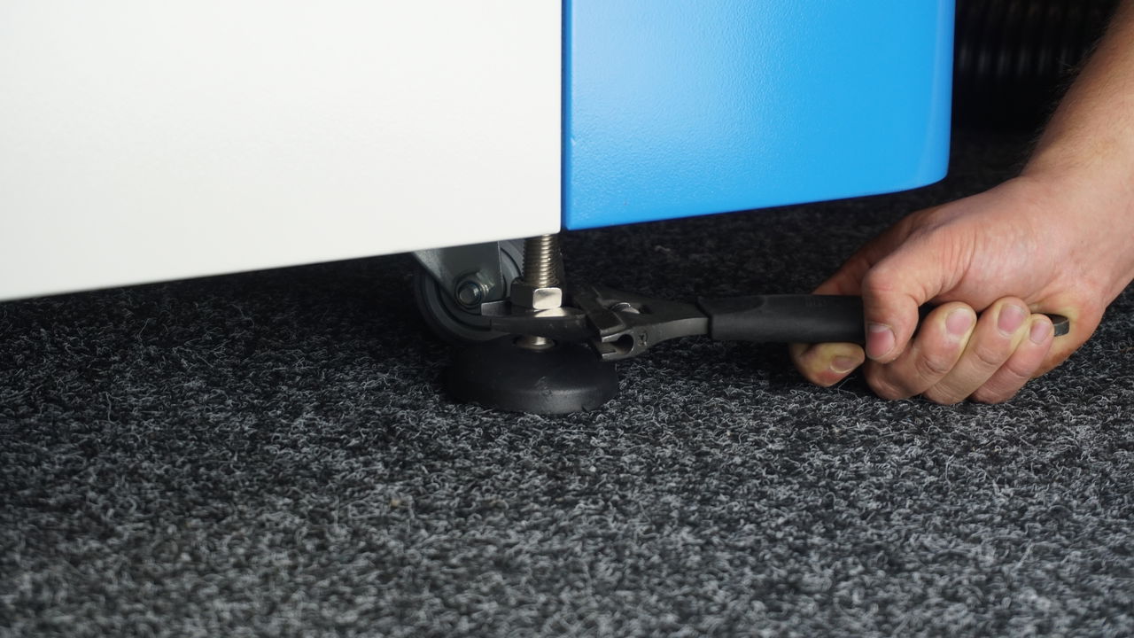
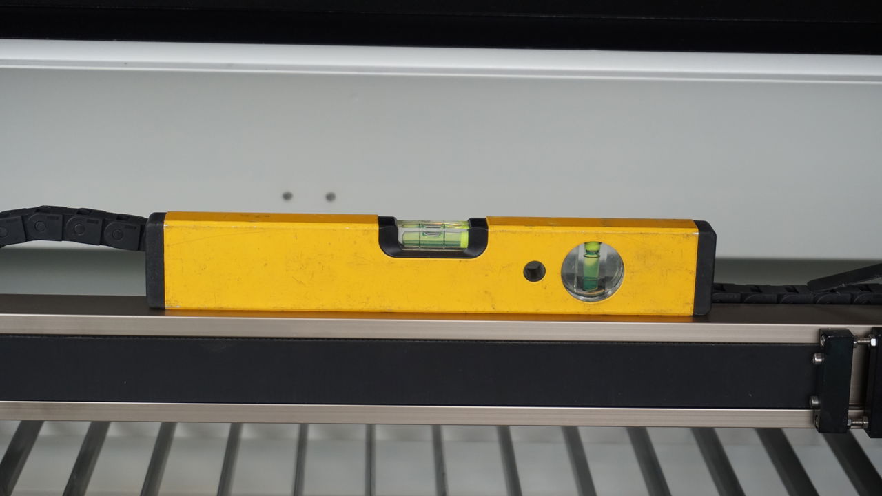
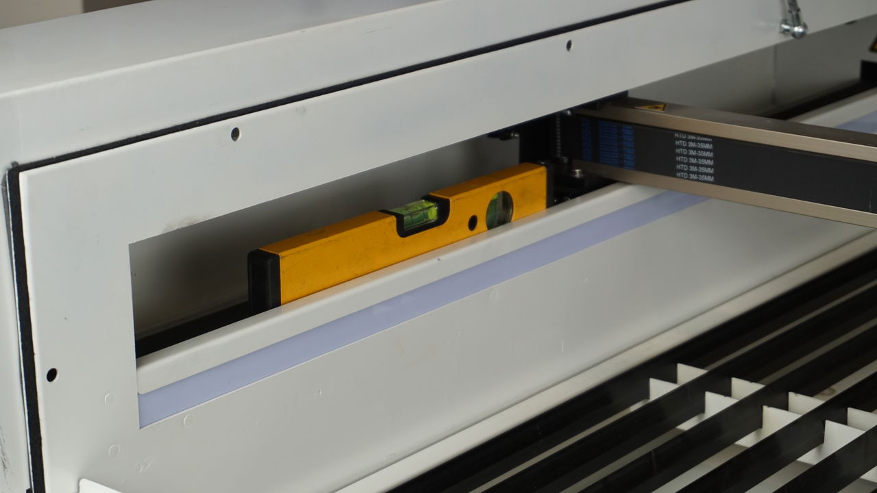
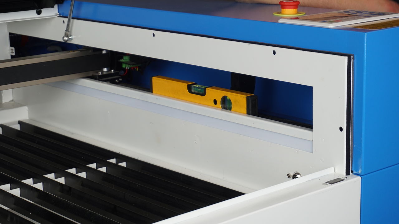
NOTE!!!
High voltage is lethal. Only qualified people may carry out these operations.
After this, if you removed the laser source from the machine, you can put it back in. Once you have installed the laser source, connect the water chiller. Make sure the water hoses are attached to the water chiller correctly. Plug the water chiller into an external outlet. Turn on the water chiller and check to see if the water flows from left to right through the laser source, seen from the back of the laser machine. If it flows from right to left, change the water hoses to get the cooling water flowing correctly. Also, make sure there are no air bubbles left in the water in the laser source, these can cause damage that could cause the laser source to break. Check the following article for more information: [water chiller in top condition.](/en/peripherals/water-chiller/the-water-chiller-in-top-condition)
Once there are no more air bubbles in the laser source, you can turn off the water chiller and then you can plug the water chiller into the laser machine, if necessary. Then you can start reconnecting the rest of the parts of the machine, such as the air pump, extraction and so on. Also, put the plugs of the laser machine back into the sockets.
When everything is connected make sure you check the mirror alignment and adjust it if necessary.
If you still have questions or want to request the help of BRM Lasers, please feel free to send us an e-mail: .
# What can you do about reflection on your material?
> What can you do about reflection on your material?
When you cut material with the laser machine, the laser beam goes through your material and comes out at the underside of your material, so to speak. Your material is either on the honeycomb table or on the slat table. Both of these are made of metal. As the laser beam passes through your material, the laser beam will hit the metal of the table. The laser beam then bounces back up, against the underside of your material. This causes you to get small burns on the underside of your material.
With the honeycomb table, this happens in several places because the table contains more metal where your material lies.
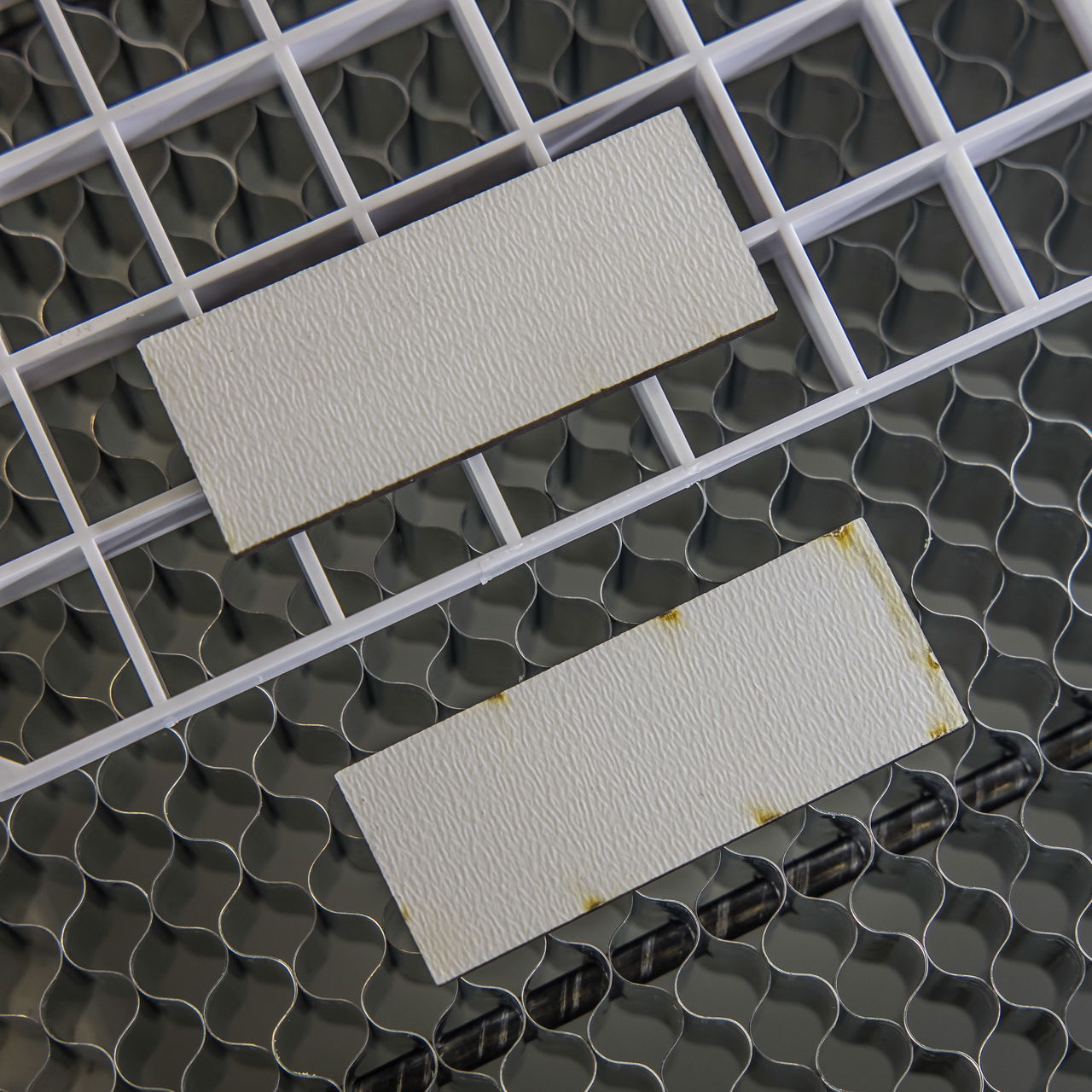
## Acrylic cutting grid
[Section titled “Acrylic cutting grid”](#acrylic-cutting-grid)
To counteract the reflection, and therefore the small burn-ins, at the bottom of your material, you can raise your material slightly. You can put something under your material that creates a distance to your honeycomb or slat table. This distance reduces the power of the reflection so that it no longer reaches your material.
You can also use an acrylic cutting grid. This is specially made to absorb excess power and in the process it also elevates your material. It is a grid made of acrylic and you put it down on the table. The laser beam comes out of your material and then cuts slightly more into the acrylic of the grid so the beam doesn’t bounce up. Because of this, you will have to replace the grid from time to time.
Because it is a grid, the fumes are properly extracted. The grate does not block this. Also, loose objects stay on the grate, they do not fall through, unless of course they are very small objects. The openings in the grid are approximately 14 by 14 mm. The grid itself is 400 by 600 mm and you can place several grids on your work area, depending on what you need in terms of surface area.
If you want to elevate your material yourself, you can do so as well. Make sure that the material you elevate with is not metal. Furthermore, the fumes must be able to be exhausted, so do not place a whole plate underneath, then the smoke cannot escape.
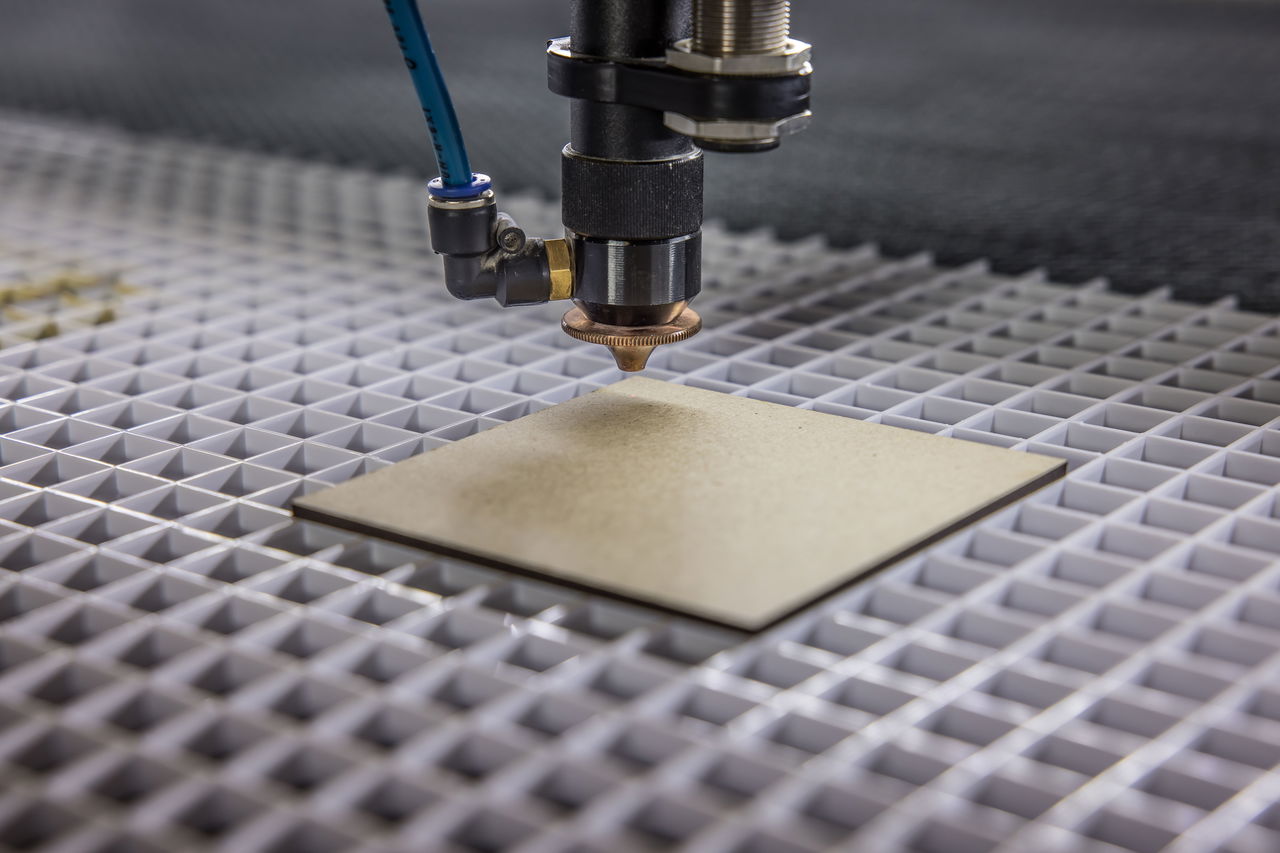
# What is a MSDS?
> It seems like the laser machine can machine all materials. Indeed, there are many materials that you can simply machine with the laser machine. But there are also exceptions.
It seems like the laser machine can process all materials. Indeed, many materials can be processed by the laser machine. But there are exceptions as well. Some materials will damage the laser machine, other materials can be harmful to lethal to your health. The MSDS can clarify this, although the MSDS will not always give good insight as to whether the material can or should be processed with the laser. You may want to read our article regarding [materials](/en/materials-and-parameters) for more information.
## What does MSDS stand for?
[Section titled “What does MSDS stand for?”](#what-does-msds-stand-for)
MSDS stands for **M**aterial **S**afety **D**ata **S**heet. If a manufacturer is going to sell a particular material, an MSDS must be available on request by the user of the material. In the MSDS, you can see what hazardous materials are in your material. You can also see the risks associated with using the material concerning safety, workers’ health and the environment. By using a MSDS, you can take the necessary safety, environmental and health measures in the workplace.
So, you can request the MSDS from the supplier of your material. You can also search by “material name” + MSDS. However, it is best to simply request the MSDS from your supplier.
When you do start researching, you may not find anything. It is important to search for the technical name. Many materials are sold under a brand name, for example, Plexiglass or Perspex. If you look at the brand name, it may be PMMA for one individual and PA for another. So it is important to look beyond the brand name when searching for the MSDS.
A material can have multiple names.
* Technical name: PMMA
* Brand name: Plexiglass, Perspex
* Common name: Acrylic
This is quite confusing, but the manufacturer will always be able to give you the technical name.
If you received the MSDS, the first thing you look at is the components to see if it contains anything harmful.

## Which components are not recommended?
[Section titled “Which components are not recommended?”](#which-components-are-not-recommended)
It is important to check if the material contains the following components because they are a health hazard, lethal and cause damage to the machine:
* Anions
* Fluoride **F-**
* Chloride **Cl-**
* Bromide **Br-**
* Iodide **I-**
* Mercury **Hg**
Other components are not necessarily safe; you still must be aware of the fumes that are released when the material is processed. The safety hazard information is also in the MSDS.
NOTE!!!
Anions and Chloride are very hazardous to one’s health. BRM Lasers strongly recommends not to work with PVC or other materials containing Anions / Chloride with a laser machine. Processing these materials will terminate the warranty on your machine.

## Safety measures
[Section titled “Safety measures”](#safety-measures)
You will also find first aid measures. Make sure everyone working near the machine is aware of these measures. The inhalation measures are particularly important because fumes are released when materials are processed in the machine.
Check the firefighting equipment and ensure you have the proper extinguishers within easy reach. At least one CO₂ extinguisher should be present with the laser machine. Also, check the machine’s manual for fire precautions and comply with them.
Check the MSDS to see what measures apply when the substance is released and how to store it. You will also see what precautions to take regarding personal protection.
Last of all, you check toxicological information and instructions for disposal of the material.
Once you have determined your material does not contain hazardous substances and you take the proper precautions you can start working with your material.
If you are looking for the right parameters for your material, please check this page: [How can I find the right parameters for my material?](/en/materials-and-parameters/materials/how-to-adjust-for-a-material)
If you still have questions about an MSDS or if you can’t work it out, feel free to submit a [ticket](/en/contact) with your question. Be sure to include your MSDS so we have the correct information right away.
# BRM90130-X Metal-Acrylic
> The BRM 90130-X can cut metal and non-metals. In the text below, you will find more information about differences in nozzles, lenses and lens positions.
The BRM 90130-X can cut metal and non-metals. In the text below, you will find more information about differences innozzles, lenses and lens positions.
## Nozzles
[Section titled “Nozzles”](#nozzles)
The machine came with three different nozzles.
* The first one is the 1.5 mm nozzle. This means that the diameter of the hole in the nozzle is 1.5 mm. It is used to cut metals and ensures that little oxygen passes through it. This results in a nice clear, thin line. Because it is a small opening, it requires a perfect mirror and lens alignment, as the laser beam must be able to pass through the opening exactly. It is impossible to use this nozzle for non-metals.
* The second one is the 2 mm nozzle. This means that the diameter of the hole in the nozzle is 2 mm. It is also used to cut metals. This nozzle allows more oxygen to pass through than the 1.5 mm nozzle. This results in a clean cutting line that is just a bit coarser than when using the 1.5 mm nozzle. But it is a bit easier to align the mirrors and lens because the beam can pass through a slightly larger opening. It is impossible to use this nozzle for non-metals.
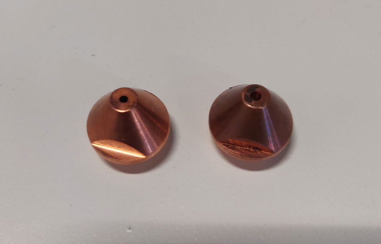
*Left: 1.5 mm nozzle. Right: 2 mm nozzle*
* The third one is the 3 mm nozzle. It is used solely to cut non-ferrous materials such as acrylic and wood. It resembles a UFO, a point with a larger disc around it. It is impossible to use this nozzle for metals.
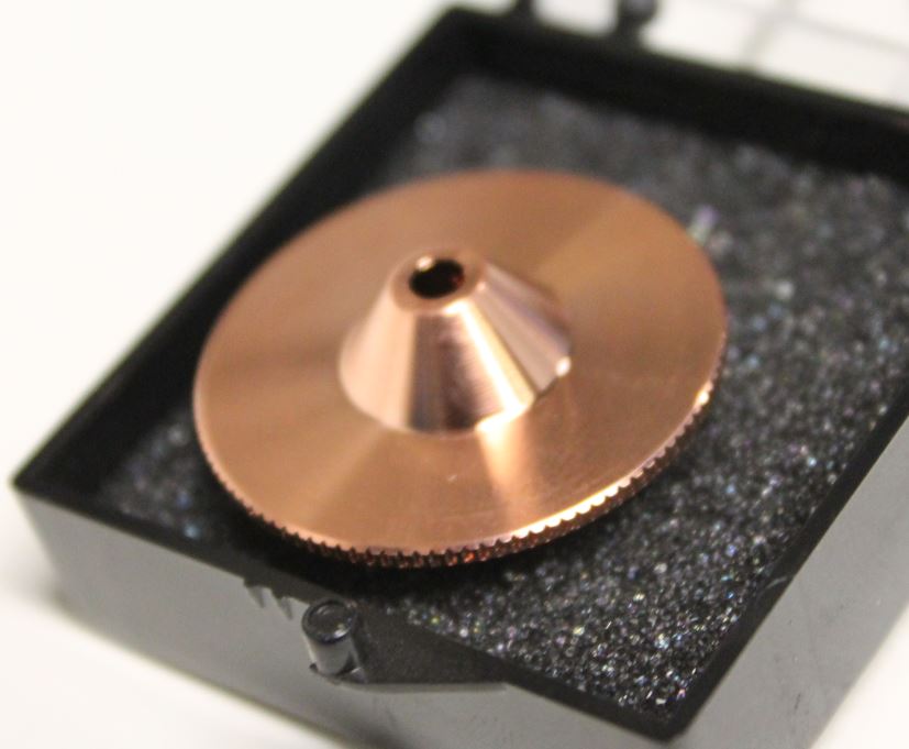
*3 mm nozzle*
## Lenses
[Section titled “Lenses”](#lenses)
Not only do you use a different nozzle, but you also use a different lens and lens holder depending on the material to be processed.
The lens used to cut metal is the 63.8 mm lens with a diameter of 25 mm. This means that the lens holder has a larger opening. The lens to cut non-metals is the 101.6 mm lens with a diameter of 20 mm. This lens is placed in a lens holder with a somewhat smaller opening. Cutting with a 63.5 mm (Ø 20 mm) lens is also possible, but not common.
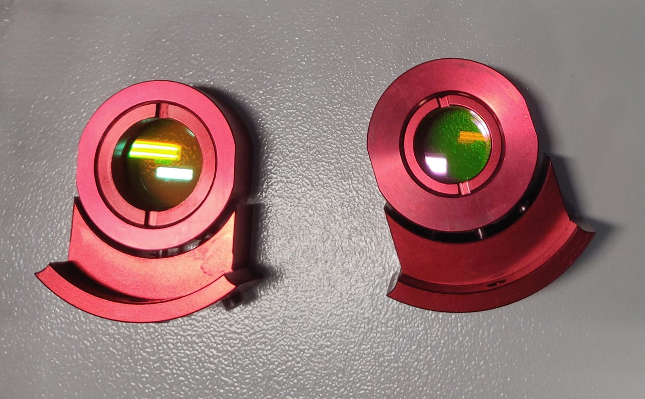
*Left: lens holder for metal. Right: lens holder for non-metal*
The lens holder is inserted into the laser head. There are two openings in the laser head. One for the lens holder, the other for an empty holder. The empty holder is needed to prevent oxygen from escaping. If oxygen escapes, the cutting line will become imperfect. In addition, the empty holder ensures that no smoke or dust can get onto the lens.
The lens used to cut metal is placed in the lens holder with the larger opening. The entire lens holder is placed in the lower opening. Insert the empty holder into the upper opening. Position the appropriate nozzle on the laser head; the 1.5 mm nozzle or the 2 mm nozzle. Do not over-tighten the nozzle. Fixed is fixed.
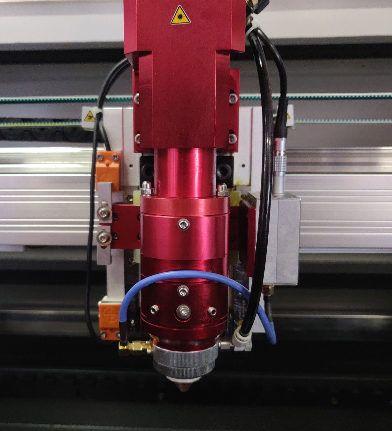
*Metal lens holder in the bottom position.*
If you are going to cut non-metal, place the 101.6 mm lens in the lens holder with the smaller opening. The lens holder is placed in the upper opening. Place the empty holder in the lower opening. Position the correct nozzle on the laser head, the 3 mm nozzle, with the UFO-shape. Do not over-tighten the nozzle. Fixed is fixed.
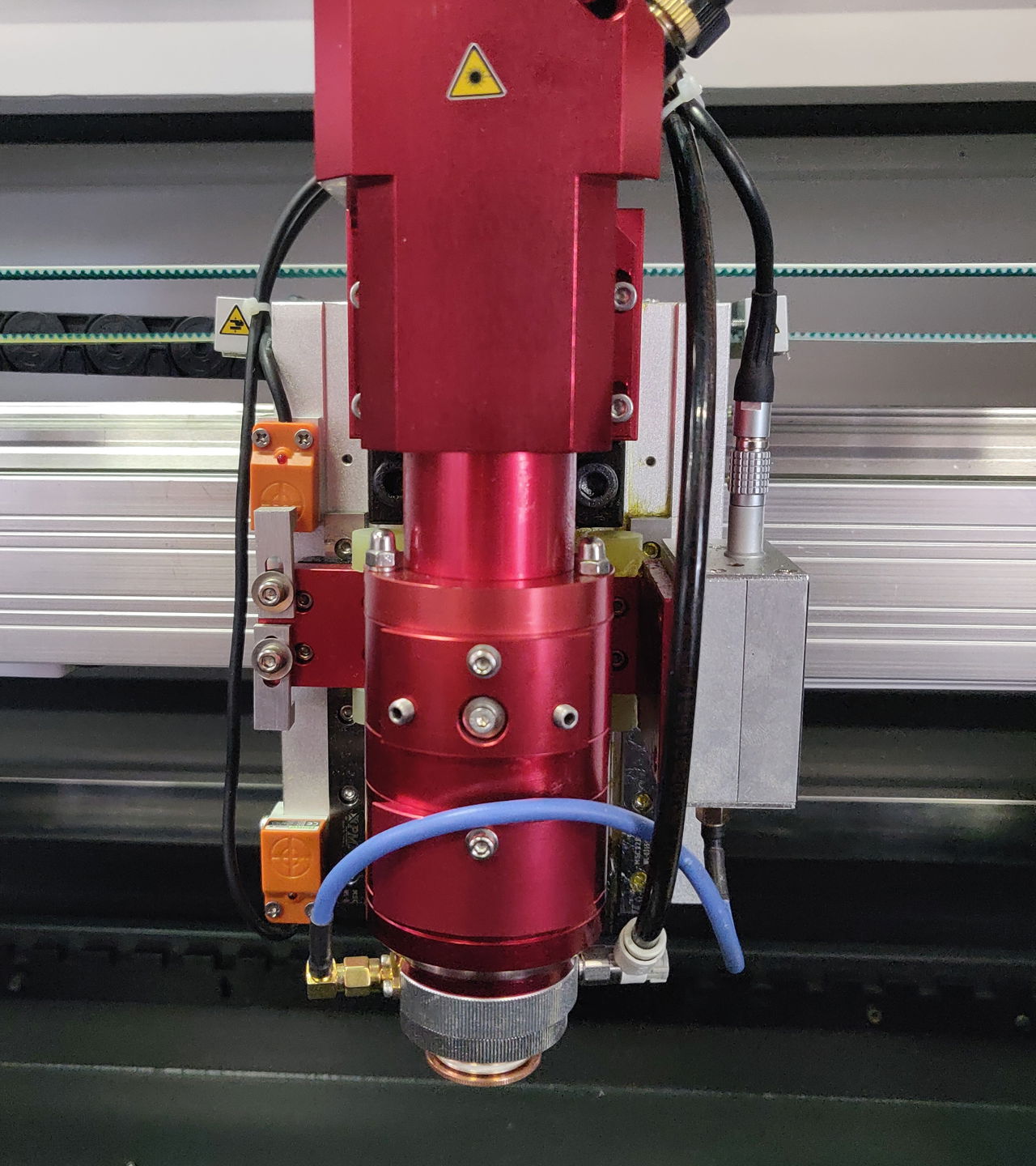
*Non-metal lens holder in the upper position*
When using the 63.5 mm lens (Ø 20 mm) for cutting non-metals, it is placed in the lens holder with the smaller opening.The lens holder is placed in the lower position. Position the empty holder in the upper position.
## Acrylic to metal
[Section titled “Acrylic to metal”](#acrylic-to-metal)
Switch on the machine. Make sure that the Metal-Acrylic switch is on Metal. This switch is located on the right side of the machine on the BRM Original. Place the holder with the metal lens and attach the 1.5 mm or 2 mm nozzle.
Press ‘Follow Adjust’. This button is located on the right side of the machine. Follow Adjust provides the correct focus height so the cutting line will be optimal. Open the oxygen from the cylinder. You are now ready to cut metal.
Make sure to only cut stainless steel or steel with a maximum thickness of 1.2 mm. It is impossible to cut copper, aluminum, zinc, etc.
If the cutting line is not clean or looks like welding, this means that the cutting parameters are not optimal. Adjust the speed, power and/or oxygen.
**WARNING! It is impossible to engrave while in metal mode.**
## Metal to acrylic
[Section titled “Metal to acrylic”](#metal-to-acrylic)
Switch on the machine. Make sure that the Metal-Acrylic switch is set to Acrylic. This switch is located on the right side of the machine on the BRM Original. Place the holder with the acrylic lens and attach the 3 mm nozzle, with the UFO-shape. Set the correct focus height. This is done by moving the table up / down. Be very careful here, there is a chance of a collision with the laser head. This can cause enormous damage. When working in acrylic mode, you do not need oxygen.
It is possible to engrave acrylic, wood and metal when working in acrylic mode. When marking metal, it is important to use a laser spray such as [CerMark](/en/materials-and-parameters/lasersprays/cermark-lmm6000). This ensures that there is no reflection towards the laser source. Any reflection towards the laser source can cause it to break. If you do mark metals without a laser spray and the laser source is damaged, this is not covered by warranty! Also, by applying a spray such as CerMark, you will get a nice contrasting engraving.
[What metals can I cut with my BRM90130-X or BRM Budget90130-X?](/en/problems-and-solutions/metal-laser/what-metals-can-i-cut-with-my-brm90130-x-or-brm-budget90130-x)
# How do I find the circle pulse of the claw rotation BRM Original?
> The circle pulse is the ratio of the number of steps the motor has to do to rotate 1 x. Depending on the motor that is on the machine, the number the number of pulses is different and you also need a different value.
## I have a [BRM Original](https://www.brmlasers.com/product/pro-1300?utm-source=support-site) and a chuck rotation. Now I need to set my circle pulse but where do I find it and what is the circle pulse?
[Section titled “I have a BRM Original and a chuck rotation. Now I need to set my circle pulse but where do I find it and what is the circle pulse?”](#i-have-a-brm-original-and-a-chuck-rotation-now-i-need-to-set-my-circle-pulse-but-where-do-i-find-it-and-what-is-the-circle-pulse)
The circle pulse is the ratio of the number of steps the motor requires to rotate 1 time. Depending on the motor of the rotation unit, the number of pulses differs and requires a different value. For example, if it needs 7500 pulses to rotate once, the circle pulse is also 7500. If the motor needs 6500 pulses for one rotation, the circle pulse is 6500.
The [BRM Original](https://www.brmlasers.com/product/pro-1300?utm-source=support-site) came with a chuck rotation. Also, a USB stick was supplied along with a checklist. On this USB stick and the checklist, you will find the circle pulse. You can still retrieve the circle pulse yourself if you no longer have the USB stick or checklist.
## How do I find out the circle pulse myself?
[Section titled “How do I find out the circle pulse myself?”](#how-do-i-find-out-the-circle-pulse-myself)
Make sure you have materials you can test on. A cardboard roll, for example, can be very useful. The test material should be truly round and not conical! Measure the diameter of your test material. This is very precise; it is best to measure the diameter with a caliper if you have one. Please write down the diameter.
Place the chuck rotation in the laser machine, in line with the bridge (X-axis). Position the rotation with the motor to the left on the working area, otherwise, your drawing will be mirrored. This does not matter for testing, but it is inconvenient if this happens when you start to process new material.
Position the laser head in the upper right corner of the working area. Press “Origin” on the display on the laser machine. Turn off the laser machine and insert the plugs of the rotation into the connectors. You will find the connectors on the right side, inside the cabinet. Once you have connected the plugs you can close the cover. Next, go to the switch panel on the right side of the machine. Here is a switch called the Y/U switch. Make sure you have the switch set to the U position. If the switch is still on the Y, then you need to move the switch to the U.
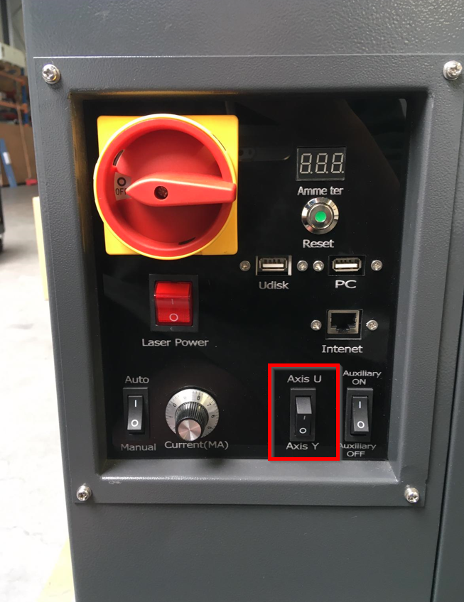
Turn on the laser machine again following the normal procedure. You will notice that the laser head will not move in the Y direction. If you press the Y- or Y+ buttons on the display, the rotation will start to rotate. The X-axis will also work as usual. Once the laser machine is switched back on completely, you can start clamping your test material in the chuck rotation. Make sure it is secured and cannot slip away. Move the X-axis to the center of your product. Since the Y-axis does not work, you will have to manually move the bridge towards you to position the laser head above your material. Make sure the nozzle (the point at the bottom of the lens shaft) is above the highest point of your test material. Now adjust the focus height. On the display, press the Origin button.
Then, in the laser software, draw a square of 2 by 2 cm. Set the parameters to cutting. However, take the speed and power that you would use for engraving. After all, you want to make a mark on your test piece; you don’t want to cut through it.
After that, go to the **Output** tab. Check the box next to **Enable rotate engrave**. Take a Circle pulse of 7000. Next to Diameter, enter the **diameter** of your test product. Now send your file to the machine.
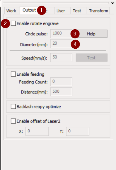
Retrieve the file in the machine. Start ‘cutting’ the file. Once the machine is ready, remove the product from the chuck rotation. Measure the line across the curve of the product. It is important to measure properly, it is best to use a tape measure here.
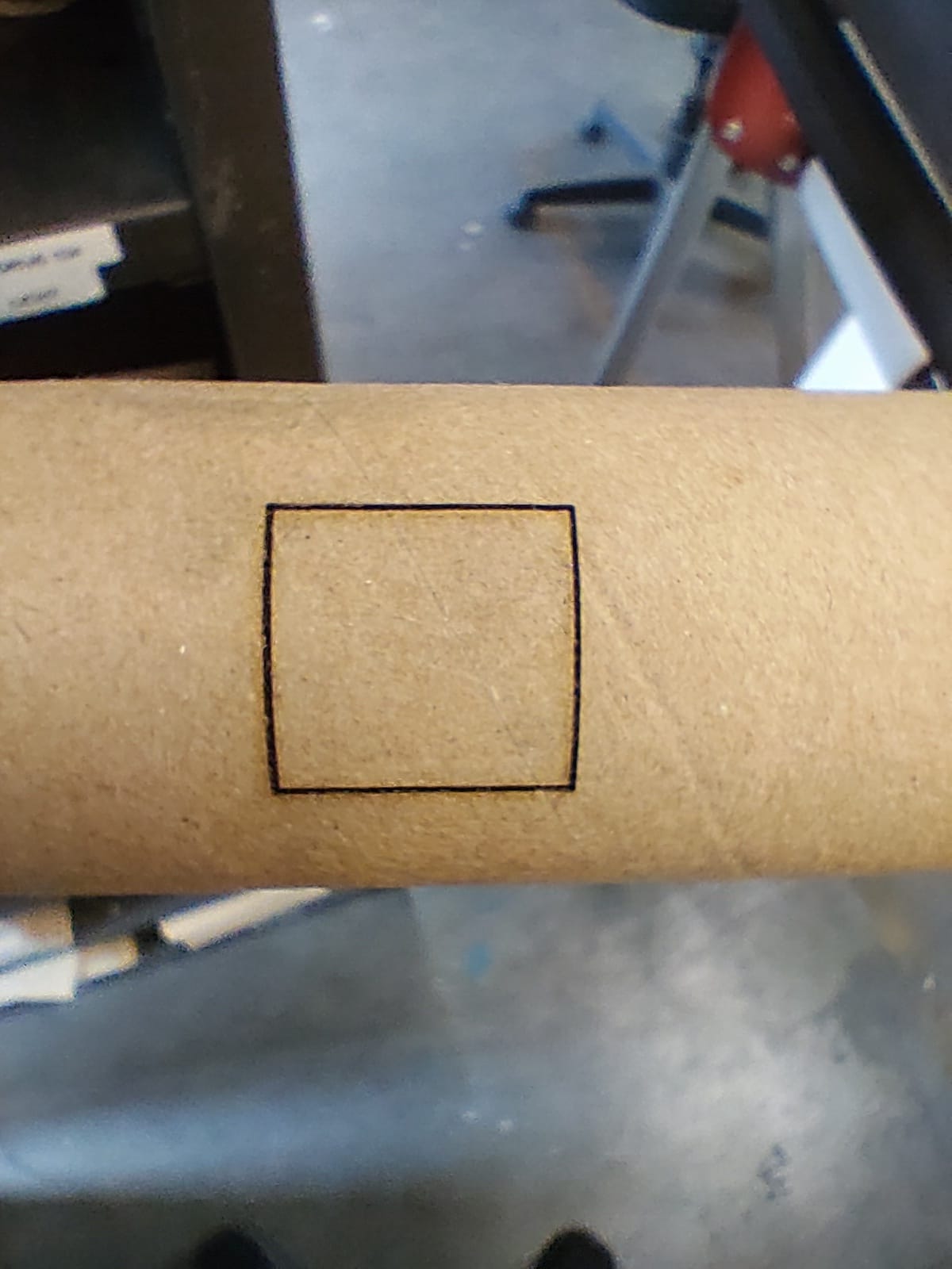
Most likely the line across the curve is not exactly 2 cm. It will be larger or smaller. Try a circle pulse of 6500 or 7500 and see what happens. This way you can, first in some larger steps and when you are closer, in small steps determine the circle pulse. Keep adjusting the circle pulse until the line across the curve is indeed 2 cm.
If you can’t work it out or have any questions, please feel free to submit a [ticket.](/en/contact)
# How do I make my Slim machine and rotation ready for use?
> When you want to start working with the Slim and rotation there are a number of steps to follow.
Guide for setting up the [BRM Slim](https://www.brmlasers.com/product/slim-1300?utm-source=support-site) rotation unit.
When you want to use the rotation unit, there are certain steps to follow.
The rotation for the [Slim](https://www.brmlasers.com/product/slim-1300?utm-source=support-site) is a roller rotation by default. That means there are 4 rollers, 2 of which are powered by a motor. The other rollers can slide forward and backwards depending on the length of your product. You adjust this to make sure your product has enough support. The rollers can spread about 30 cm apart. If your product is longer, it will stick out. Be careful that your product does not stick out too far, because it may start to move and change position during rotating.
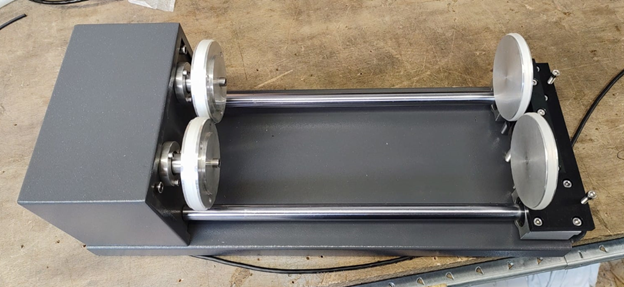
The roller rotation comes with a chuck plate as well. You can attach this to one of the rollers with 3 threaded ends and bolts. The chuck must be attached to one of the rollers powered by the motor.
With the chuck plate, you can clamp a product.
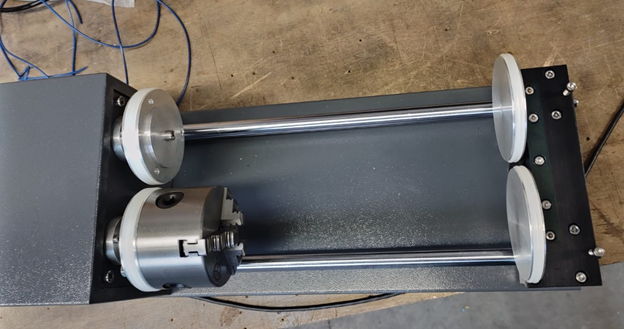
## Roller rotation
[Section titled “Roller rotation”](#roller-rotation)
When you want to use roller rotation, it is important to measure one of the rollers first. You will need its diameter later. Measure the outer diameter of the roller, from rubber to rubber. That comes pretty precise, so use a caliper. Please write down the diameter.
Move the laser head with the buttons to the top right of the machine. Press Origin on the display. Be sure to start from the “User origin” in the software.
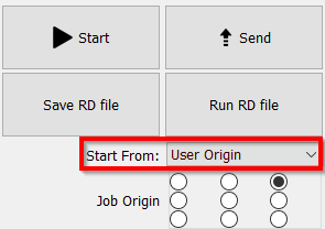
Next, remove the table from the machine. Position the roller rotation in the machine with the motor to the left. Make sure the cable is not underneath the rotation.
Connect the cable with the plug to the machine. On the right side of the machine is a wall plug where the plug of the rotation can be connected.
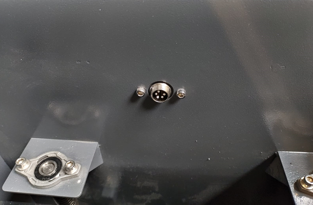
Now reset the axes. Because you have placed the axes in the upper right corner and have “User origin” selected in the software, there will be no collision between the laser head and roller rotation / product. Once the machine has finished the reset, you can place your product on the roller rotation.
Move the laser head towards your product. You will notice that you cannot move in the Y direction using the buttons on the display. You can, however, move the X-axis using the buttons. When the laser head is positioned correctly in the X direction, you can manually move the laser head in the Y direction correctly. Position the laser head above the center (highest point) of your product. Adjust the focus height. Be careful when using the autofocus sensor, we recommend not using the autofocus sensor when using the rotation unit. It is best to manually set the right focus height.
If there is too much distance between your object and the laser head, you can move the laser head back slightly. Raise the Z-axis slightly with the Z+ button. Then put the laser head back above the highest point of your object.
After that, in the LightBurn software, go to Tools => Rotary setup.
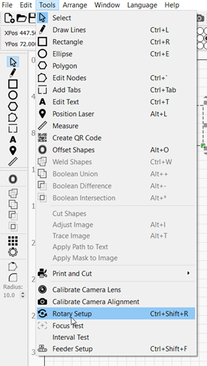
Please make sure the circle for **Roller** (1) is black. Also, check that **Enable Rotary** (2) is on. You can see that it is on because the slider will be green.
Enter 10000 for **Steps per rotation** (3). That, together with the diameter of the roller, will ensure that your program has the correct dimensions.
At **Roller diameter** (4), enter the diameter of the roller you wrote down at the beginning.
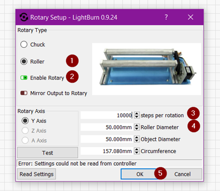
You can enter the diameter of your object. The software then calculates for you the circumference of your object but the software does not need these values to function. You can leave out the Object Diameter and Circumference.
Click **OK** after you have entered the required data.
Draw a square of, say, 2 by 2 cm. You are going to cut this one lightly to check that the dimensions are indeed 2 by 2 cm. Set the speed and power and send the file to the laser machine. Be careful! You want the lines to be visible but not cut through the material. Set the mode to cut \[Line] but use parameters you would use for engraving!
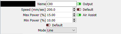
When the lines are visible on your product, it is important to measure the line running across the curve. Do this with a tape measure to get the measurement right.
If the line is not 2 cm but larger or smaller, you will need to adjust the ‘Steps per rotation’. You entered 10000, it may be that it should be 9998 or 10002, for example, to get the exact size. You will have to try some to get the exact number.
When the size is correct you can start working with the roller rotation. Make sure to write down the steps per rotation so you don’t have to do this every time you want to use the rotation.
## Chuck rotation
[Section titled “Chuck rotation”](#chuck-rotation)
When you want to work with the chuck rotation you have to attach the chuck to one of the rollers powered by a motor. There are 2 rollers with 3 holes in them. Choose one of the rollers. With the rotation is a small bag containing 3 threaded ends and bolts. Screw the threaded ends a bit into the chuck, on the back of the chuck you find there are 3 holes. Do not screw the threaded ends in too far.
Place the chuck in front of the roller and insert the threaded ends through the holes in the roller. Tighten the chuck with the bolts. Make sure it is tightened securely.

Position the laser head to the right rear of the machine and press Origin on the machine display. In the software, make sure to start from the ‘User origin’.

Position the rotation in the machine with the motor to the left on your table. Connect the cable with the plug to the machine. On the right side of the machine is a wall plug where the plug of the rotation can be connected.

Once you have connected the rotation you can reset the machine. Because you put the laser head on the top right and the software is on User Origin, there will be no collision with the rotation. Measure the diameter of your object. Use a caliper to measure the diameter. Write this diameter down, you will need it later.
Clamp your product in the chuck. Make sure your product is clamped securely.
Move the laser head towards your product. You will notice that you cannot move in the Y direction using the buttons. You can, however, move the X-axis using the buttons. When the laser head is positioned correctly in the X direction, you can manually move the head in the Y direction correctly. Position the laser head above the center (highest point) of your product. Adjust the focus height. Be careful when using the autofocus sensor, we recommend not using the autofocus sensor when using the rotation unit. It is best to manually set the right focus height.
If there is too much distance between your object and the laser head, you can move the laser head back slightly. Raise your table slightly with the Z+ button. Then put the laser head back above the highest point of your object.
After that, open the LightBurn software on your computer. Go to Tools => Rotary setup.

Make sure the circle for **Chuck** (1) is black. Make sure **Enable Rotary** (2) is on. You can see that it is on because the slider turns green. At **Steps per rotation** (3) enter 10000. This, together with the correct diameter of your object, will ensure that your program has the correct dimensions. At **Object Diameter** (4) enter the diameter of your object, which you wrote down at the beginning. The software will calculate the circumference by itself.
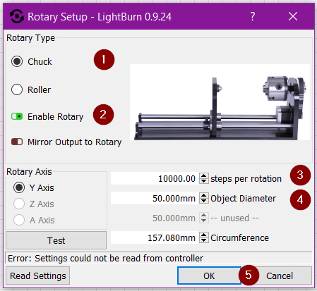
Click OK after you have entered the required data.
Draw a square of, say, 2 by 2 cm. You are going to cut this one lightly to check that the dimensions are indeed 2 by 2 cm. Set the speed and power and send the file to the laser machine. Be careful! You want the lines to be visible. Set the mode to cut \[Line] but use parameters you would use for engraving!


When the line is visible on your product, it is important to measure the line running across the curve. Do this with a tape measure to get the measurement right.
If the line is not 2 cm but larger or smaller, you will need to adjust the \[Steps per rotation]. You entered 10000, it may be that it should be 9998 or 10002, for example, to get the exact size. You will have to try some to get the exact number.
When the size is correct you can start working with the chuck rotation. As soon as you want to process another object, you will have to measure the diameter of your object again and enter it into the software. If you don’t do that, the dimensions will be off.
Make sure to write down the steps per rotation so you don’t have to do this every time you want to use the rotation.
How do I go from rotation back to working on the table? Remove your object from rotation unit. If necessary, move the laser head backwards to have more space to remove the object.
Unplug the rotation from the wall plug. Lift the rotation out of your machine. If you have removed your table from the laser machine you can put it back.
In the LightBurn software, go to Tools => Rotary setup.

Disable **Enable Rotary** (1). You can see that Enable Rotary is off because the slider turns red. Then click **OK** (2).
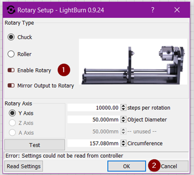
After you have completed these steps you need to reset the machine. The laser head will return to the upper right corner. You can now start cutting/engraving a flat product again.
## The product is conical, can I adjust the rotation?
[Section titled “The product is conical, can I adjust the rotation?”](#the-product-is-conical-can-i-adjust-the-rotation)
If you have a conical product, it will still have to be parallel to the X-axis. If this is not parallel, you will not have the same focus height everywhere and the engraving will not be done properly. To solve this, there is a levelling screw on the rotation that allows you to adjust the height of the rollers. You can only use it when using the rollers. It is not an option if you are using the chuck. After you have the rotation connected in the machine you place your product on the rollers. Then rotate the levelling screw to make sure your product is parallel to the X-axis.